makerdad
makerdad
Stepper Motor Success
After a few days of struggling with stepper motor controls, I finally got everything working reliably last night. There were a lot of learnings along the way, most of them not very well explained on most tutorials I found online.
My problem was essentially that I have a ridiculously powerful set of steppers. I kept referring to them as NEMA-14, but while reading this guide from Adafruit, I learned that NEMA nomenclature doesn’t mean much other than enclosure size.
So I searched the serial number and found the product specs sheet on Pololu. I bought these many years ago so I had no idea what the specs were.
As it turns out, specs are critical when dealing with steppers. You specifically need to know the current requirements per coil (amps per phase and resistance per phase). In my case, it was a fairly high 1A per coil. Problem is, the motor drivers I had couldn’t supply more than 0.6A per coil, and that’s probably why they kept heating up and the motor was so erratic.
Thankfully, I also found some A4983 drivers in a motor drivers box I had in the basement. Perusing the specs showed that they are capable of 2A output! That sounded promising.
After hooking up the driver with the basic setup, I plugged it in to a 24V supply. This was the other learning. Even though the stepper is specced at 2.7V, that doesn’t mean much. They are very power hungry and work more efficiently under higher voltages.
Another thing you have to do with A4983 is to adjust the output current using the potentiometer on board. This can be done using the REF pin and doing a simple calculation. I set it to output roughly 0.8A for starters. This guide on RepRap was excellent for figuring this out.
In any case, I plugged it in and… Nothing happened. I even soldered some pins again since they didn’t look great, and also tried a second driver. But no success. Motor was quiet and there was no movement at all.
This wasn’t too surprising to me because I had tried to make these drivers work back in October for a Halloween project. But this time I was determined. Back to the specs I went.
That’s when I noticed something weird. There was an obscure reference to the board requiring voltage input from the logic controller. Even though I was powering the board and the Arduino separately, A4983 still wanted the 5V from Arduino into the VDD pin. I plugged it in, and the stepper burst into motion as expected!
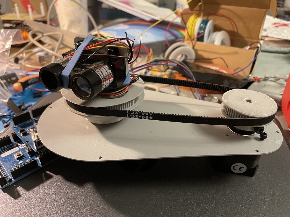
Next step was testing this alongside the LIDAR. Earlier this week, I had identified the old LIDAR unit I had as a Garmin LIDAR Lite v1. Unfortunately v1 is from 2015 and Garmin dropped support for it a while back (they are on v4 now). They have a well maintained Arduino library but I couldn’t get it to work with v1 unit I have. After much trial and error, I found an Arduino sketch that a kind soul had posted for v1. After some tweaking, I had the Garmin LIDAR Lite v1 delivering consistent results.
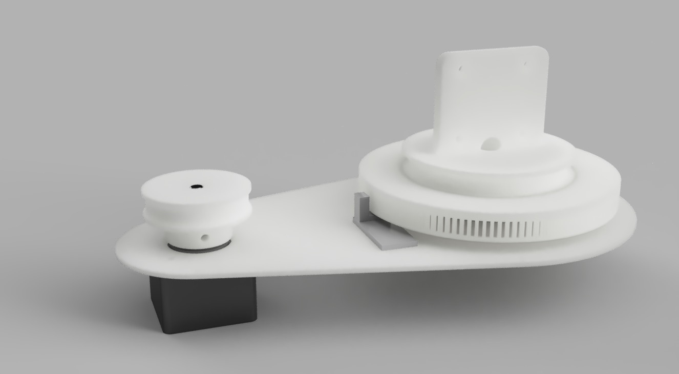
Thankfully, making the LIDAR work alongside the stepper was easy. A4983 makes stepper control a breeze. All you have to do send a HIGH to STEP pin and it steps. That’s it, no fuss. With a few lines of code, I had the stepper moving reliably and mapping position data to LIDAR distance measurements.
Of course, the stepper positional data is not reliable and I’m not planning on using it. But if I can couple this with an optical encoder, I should be able to output reliable mapping data.