makerdad
makerdad
Encoding DC Motor Steps
Now that I have successfully encoded the stepper motor position for LIDAR, I turned my attention to encoding the DC motors that I am planning to use for running the robot wheels.
There are several good examples of this online, but most use quadratic encoders (DC motors with embedded dual encoders in them, usually magnetic). Unfortunately I don’t have any such motors at hand, and I have many, many DC motors so I am hesitant to buy more.
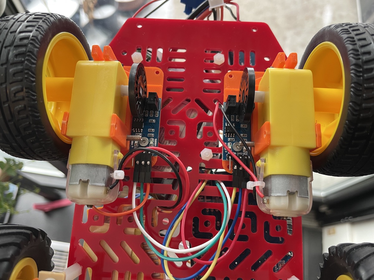
So after watching this fun little video from Sparkfun, I decided to build my own simple encoder. I already have the optical encoders with disks ready to go. So I designed and printed a motor holder that can hold the gear shaft and encoder disk in place.
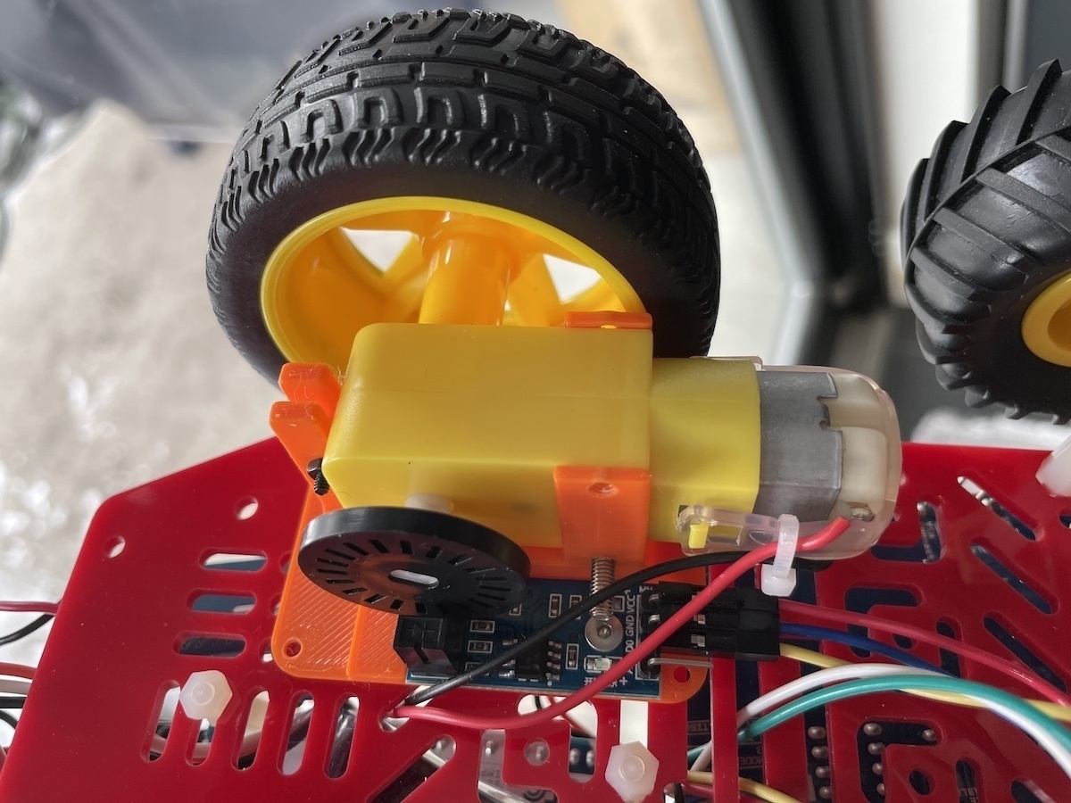
Funny enough, the biggest problem I had was soldering the cables on these flimsy 3V motors. In retrospect using the bigger 6V motors would have been a better idea. I might swap things around once I have a working prototype.
Sparkfun video comes with a handy little code snippet for speeding up and slowing down the two motors so they drive more or less equally. I adapted this for the Arduino Motor Shield and ran a few tests. It seems to be working, but hard to tell without an actual test on the ground.
I will now have to convert everything to run on a LiPo battery so I can autonomously test this on the floor. Objective is to get it to drive straight a specific distance.
Once I have reliable results, I am planning to add coupled Xbee units to be able to remotely control the robot from my laptop.