makerdad
makerdad
Driving Straight for Real Using PID
After implementing the simple straight driving sample for the rover, and integrating the XBee wireless protocol, it was time to test things out. I installed the new gearboxes (they came with motors installed and cables soldered, yay!) and did a test run. However, the first issue I ran into after switching to the battery setup was the OLED screen not starting up. I lost a bit of time on this, because the screen was actually working well when I connected the Arduino to the computer.
OLED screen uses I2C, so I figured it was an issue with the I2C discovery step and spent some time debugging it to no avail. Then I realized that the screen only worked when the serial monitor was turned on. This led me to suspect the software serial implementation, and I was right.
I was using SoftwareSerial to run the XBee serial communication module. Some research showed that SoftwareSerial has some serious performance issues. An alternative suggested was AltSoftSerial, so I gave it a try and magically things started working again! Lesson learned. One note for future though: AltSoftSerial is very well optimized, but disables PWM on Pin 10.
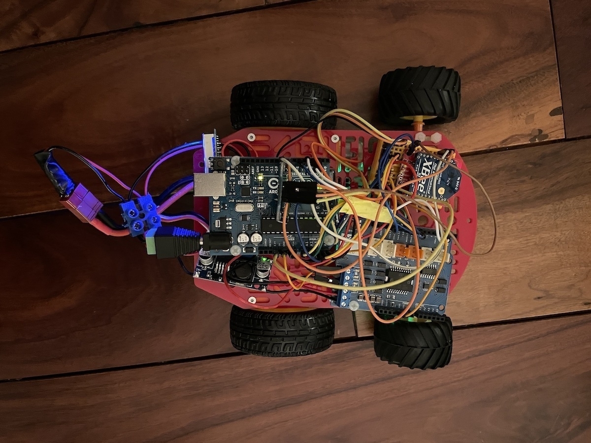
Now that everything was running smoothly, I ran my first test on the ground. Results were better, but not great. Rover was still swerving quite a bit to the left. I suspected some of this was mechanical, since I had a caster at the front and it’s not the best solution for making sure the robot is moving on a straight line. So I reworked the front into a two wheel setup. This helped somewhat and definitely removed a lot of friction, but the swerve was still there.
I also suspected that the simplistic motor speed modulation script I took from the Sparkfun sample didn’t work great. So I did some research into how this is achieved and came across a concept called a PID controller. A proportional–integral–derivative controller is apparently a logic loop that keeps adjusting an output value based on an input and an expected input value. Algorithm itself is not that complicated, but there is also a great Arduino library for implementing it that simplifies things significantly.
That said, it took me a bit of time to understand how to implement PID into my control system. PID itself is agnostic to the way it’s implemented, all it primarily cares about is the three values: input, output and setpoint. Then it runs on a specific time cycle, giving back output values.
Output is easy to understand, it’s essentially the PWM value that’s pushed out to the motor so it determines the motor speed. Input and Setpoint obviously need to be of the same unit type. In my case, they need to relate to the encoder values. What I was doing before was simply checking how close the two motor encoder values were, and varying the speed accordingly. That approach doesn’t really work with the PID controller.
Solution was to separate out the two motors completely. Instead of doing a comparative analysis, each motor needs to have its own PID controller, checking its encoder output against a preset expected value (hence the term “setpoint”). So I ended up calculating the amount of encoder clicks that are expected over a specific period of time and converting that to a time based frequency. Then I compared that to an expected frequency.
As an example, I could say that I would run the PID controller calculation every 100ms, and say that the expected encoder click change every 100ms is 50 clicks. Then I pass the actual encoder click delta in the same timeframe and the PID controller compares this and makes a decision as to how much power should be outputted to the motor (as PWM).
This article on element14 was very helpful. There is also a Zumo bot project I found that was very useful for understanding the concepts, however I didn’t end up using the implementation since the Arduino PID Library provided much better abstraction.
Of course, the actual PID implementation is much more complicated than this. There are three additional parameters: proportional, integral and derivative attributes. These are used to “tune” the PID algorithm and have it output expected results. Unfortunately tuning PID seems to be a bit of a black magic and I will have to spend some time on this.
Good news is that the initial implementation is working really well after some tinkering with it. Here is a video of it in action:
Next step is to add rotation to this flow. And then I will work on a dead reckoning implementation to have it move reliably on a specific path.