makerdad
makerdad
PID Tuning Experiments
I spent the last few days experimenting with PID algorithms and tuning parameters for straight driving using only motor encoders. There were tons of learnings along the way, and I’ll try to summarize them in this post.
First off: After a lot of frustration, I realized that there was something wrong with my motor setup. Whatever I did, there was a huge discrepancy between the two geared motors. They are identical models with the same 48:1 gear boxes. However some simple encoder analysis showed that left motor was going at around 60% the speed of the right one.
I eventually tracked the issue down to the buck converter. I was limiting LiPo voltage down to 6V using a cheap buck converter. Checking the specs, I realized that the converter was only capable of 1A output. Motors were probably trying to draw more current than 1A, since the H-bridge can provide 2A per channel!
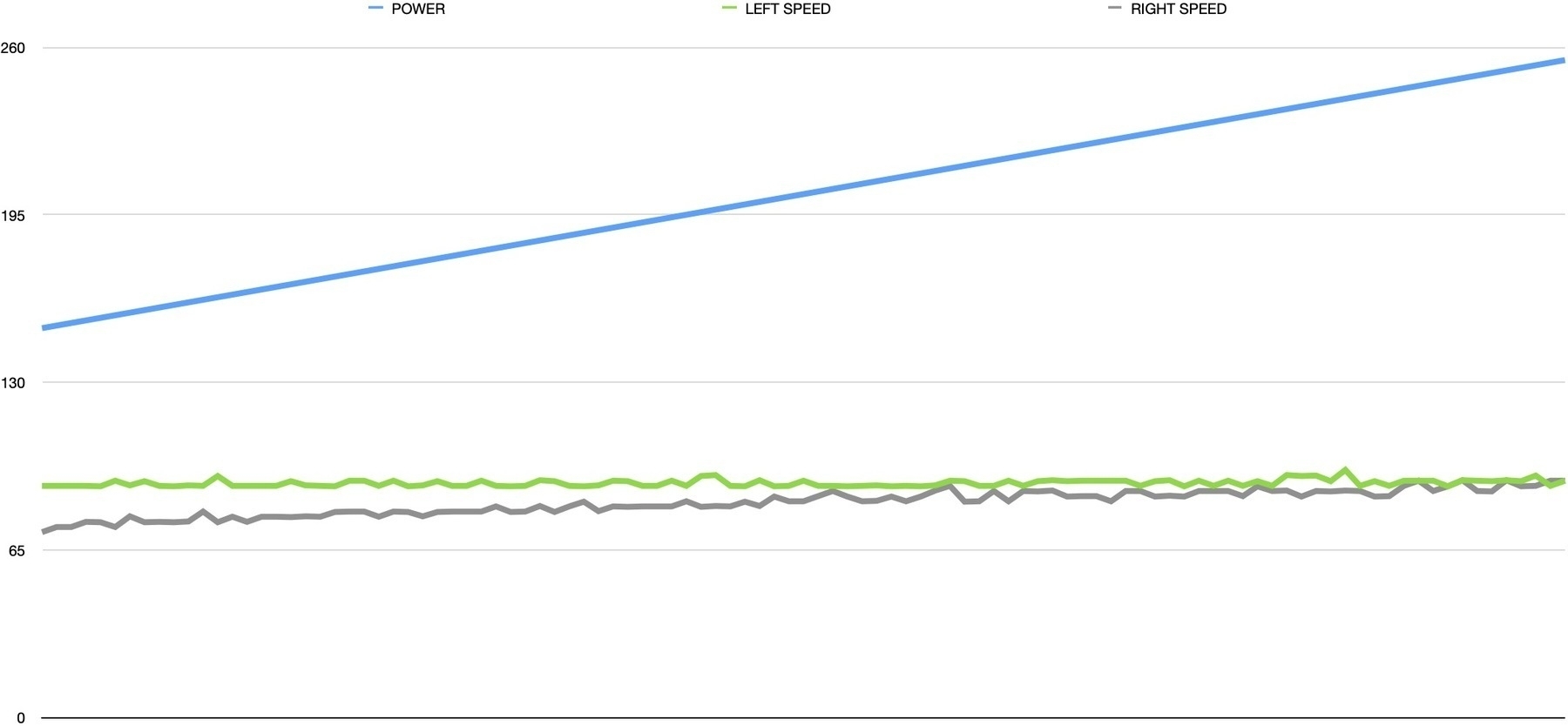
For a quick experiment, I plugged the LiPo straight into the H-bridge and the motors roared! 7.4V is probably a bit too much for them, but the speed discrepancy also disappeared. I also learned the importance of graphing data. Here is a simple speed calculator that increases motor speed every 500ms and logs the speed from each encoder:
int motorPower = 100;
int motorBias = 0;
double leftSpeed, rightSpeed = 0.0;
long lastCheckTime, nowTime = 0;
long lastLeftTurns, lastRightTurns = 0;
uint32_t leftDelta, rightDelta , timeDelta = 0;

lastCheckTime = millis();

while (motorPower <= 255 - motorBias) {
    analogWrite(PWM_A, motorPower - motorBias);
    analogWrite(PWM_B, motorPower + motorBias);

    delay(500);

    nowTime = millis();
    leftDelta = leftTurns - lastLeftTurns;
    rightDelta = rightTurns - lastRightTurns;
    timeDelta = nowTime - lastCheckTime;

    leftSpeed = (double)leftDelta / (double)timeDelta * 1000.0;
    rightSpeed = (double)rightDelta / (double)timeDelta * 1000.0;

    lastCheckTime = nowTime;
    lastLeftTurns = leftTurns;
    lastRightTurns = rightTurns;

    Serial.print(motorPower);
    Serial.print(F("\t"));
    Serial.print(leftSpeed);
    Serial.print(F("\t"));
    Serial.print(rightSpeed);
    Serial.println();

    motorPower += 1;
}
As a bonus, this outputs tabulated data into the serial monitor, which you can easily paste into a spreadsheet for charting. Here you can see the increasing motor power and the speed discrepancy actually disappearing as the motors get closer to full power:
Now that I was more confident with the power requirements and mechanics working well, I went back to the PID implementation. I had experimented with several methods before and upon further reflection, decided that a single PID controller that optimizes for minimum difference between motor speeds is the way to go:
double PID_setpoint = 0.0; double PID_output = 0.0; double PID_input = 0.0; const double Kp = 5.0, Ki = 0.01, Kd = 0.1; long nowTime;
PID PIDController(&PID_input, &PID_output, &PID_setpoint, Kp, Ki, Kd, DIRECT);

...

PID_input = (double)leftTurns - (double)rightTurns;

PIDController.Compute();

if (PID_output < 0.0) {
  leftMotorDirection = (PID_output > -50.0);
  rightMotorDirection = true;

  digitalWrite(DIR_A, rightMotorDirection ? LOW : HIGH);
  digitalWrite(DIR_B, leftMotorDirection ? HIGH : LOW);

  outputLeft = (POWER_OFFSET / 2) + (PID_output / 2);
  outputRight = (POWER_OFFSET / 2) - (PID_output / 2);
} else if (PID_output > 0.0) {
  leftMotorDirection = true;
  rightMotorDirection = (PID_output < 50.0);

  digitalWrite(DIR_A, rightMotorDirection ? LOW : HIGH);
  digitalWrite(DIR_B, leftMotorDirection ? HIGH : LOW);

  outputRight = (POWER_OFFSET / 2) - (PID_output / 2);
  outputLeft = (POWER_OFFSET / 2) + (PID_output / 2);
}
In this sample, I have the PID_setpoint targeted at zero. This is because we are calculating based on the delta between left and right motor encoder values. If they were going at exactly the same speed, the values would both be zero, so that’s what the PID is trying to achieve.
Things get a bit gnarly in the PID_output analysis, since we need to convert this single value into a meaningful output for the two motors. To complicate matters, motors can go forwards and backwards, which needs to be extracted from the same parameter.
This is when I finally got to the point of tuning the PID algorithm. Some research showed that a simple approach is to do the following:
- Set all values (Kp, Ki and Kd) to zero
- Increase Kp until the response is steady oscillation (in my case, motors getting faster and slower back and forth)
- Increase Kd until oscillations go away
- Repeat these steps until Kd increase does not stop the oscillations
- Once Kp and Kd are stable, increase Ki until it gets you to the setpoint with the number of oscillations desired
I got the implementation to a point where it steadily oscillates between one motor and the other, which was really promising. Having played with this setup for a couple of weeks though, I am starting to feel that I am causing myself more trouble than it’s worth by trying to get a stable implementation using cheap hardware. The 3V toy motors I am using are very unstable, and the lack of PWM range on them (due to lack of torque) means the PID doesn’t have a lot of room to play with.
After thinking this through a bit more, I decided that moving to a fresh rover platform, using the learnings from v1, would be best. I found some 12V geared, encoded motors online and ordered them. I am going to begin designing a custom rover on Fusion 360 and see where that gets me. Stay tuned!