makerdad
Rover Hardware Lessons
As I was putting together the Rover v2, there were quite a few lessons along the way, mostly about hardware. I’ll capture them here for posterity.
Handling Power Since I have two motors for driving and another for the LIDAR, I had to use two L298N modules, with different input voltages. I already had a voltage booster for the drive motors, getting 7.4v from the LiPo and boosting it to 14v (12v for motors + 2v for the module). I thought I could simply plug in a direct line from the LiPo for the other module, since the LIDAR motor is 6v. In practice this proved to be unreliable. Without a booster, there was a lot of variability in the current and it caused stalling issues with the motor. Once I added a secondary boost to 8v, it started humming along as expected.
Sharing Logic Power L298N modules have a very useful two-pin bridge for allowing battery power to be bucked down to 5v and passed back through to the microcontroller. Problem is having to fit on the little hat to turn this on and off constantly when switching between programming mode (Arduino powered by USB) and mobile driving mode.
I ended up adding a second flip switch to the control panel on the rover to make this easy. Now I can flip between mobile vs. plugged mode at any time.
Preventing Motor Stall I noticed that the LIDAR motor needs an initial power boost to start turning. This meant that the default PWM sometimes wouldn’t be enough to generate the torque needed for the initial move and the motor would get stuck. Solution was actually easy: Start with a higher PWM and slowly bring it down to the desired level. This ensures the motor always turns properly.
Adding PID for LIDAR Motor Since I had quite a bit of experience dealing with PID, adding one for the LIDAR motor was relatively easy. I added a simple delta check to make sure it’s turning at the desired speed. This ensures that the LIDAR can capture scans at a fairly constant rate, and the degree distribution is more even.
Hardware Interrupts Despite using an Arduino Mega, I ran out of hardware interrupts. This is mainly because Mega shares two interrupts with the I2C ports. It’s non-trivial (or probably impossible) to have them work at the same time, so I had to change my port planning a bit. I found the Enable Interrupt library, which also has a great write up about PCINT capability on the Arduinos. I ended up using the A8 and A9 pins for the LIDAR detection, and Enable Interrupt made it really easy to set things up.
One downside: You can’t use Enable Interrupt alongside the excellent Encoder library, it won’t compile. However Enable Interrupt doesn’t have native support for quadrature encoders, so I had to do some more digging on this to make it work with the driving motors. In the end I settled for this Quadrature Encoder library that uses Enable Interrupt under the hood so it plays well together. Unfortunately Quadrature Encoder doesn’t seem to be supported anymore, but it’s only a few lines of code to count the turns properly. So I integrated it directly into the project.
Wheels and Traction I spent a lot of time on experimenting with different wheel configurations (probably too much). The first version had two fixed wheels at the front. This was great for going straight, very stable. Unfortunately making turns was problematic. Front wheels had too much friction and caused the back wheels to spin. This became a big issue since it caused the encoder counts to become very unreliable for odometry.
I then tried a bunch of different configurations, using a single wheel at the front. I tried building a makeshift “landing gear” style wheel, which looked really cool but didn’t work in practice (it would get stuck in weird positions). I also tried making a version of this that had limits on its Z rotation axis. That didn’t improve things either.
In the end I had to settle for a caster wheel. I am still quite unhappy about this, since the caster is too small and very noisy on hard surfaces. It also gets stuck and I had to reverse the driving direction of the rover 180 degrees, since it only worked well when it was in the back.
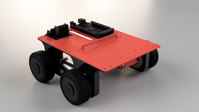
I also ended up redesigning the back wheels. I replaced them with AndyMark HiGrip wheels. They work really well, have amazing traction and look great.
LIDAR v2 Design
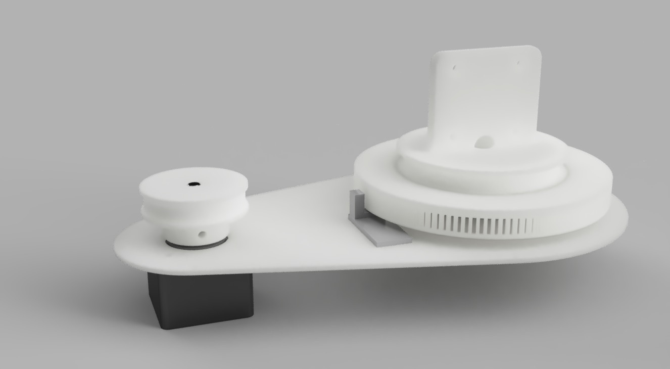
Now that the Rover v2 base is working and driving well, I am turning my attention to the new LIDAR module. After reconsidering the previous GT2 pulley based design, I decided to redesign it completely on the new Rover base, using a gear based approach.
Reasoning behind using a geared drive is fairly simple: Pulley and timing belt approach didn’t necessarily create a smooth drive mechanism like I had imagined. It also takes up a lot of space and it’s a nightmare to calculate for. Finally, printing GT2 pulleys doesn’t generate very clean results on the 3D printer, which in turn contributes to lack of smoothness.
So there are lots of reasons to simplify the design with this version. I kept the bearing the same, but learning from the previous version, made an extrusion that can be detected by the QRD1114, which will be placed conveniently underneath. I also have a nice little lid for the LIDAR.
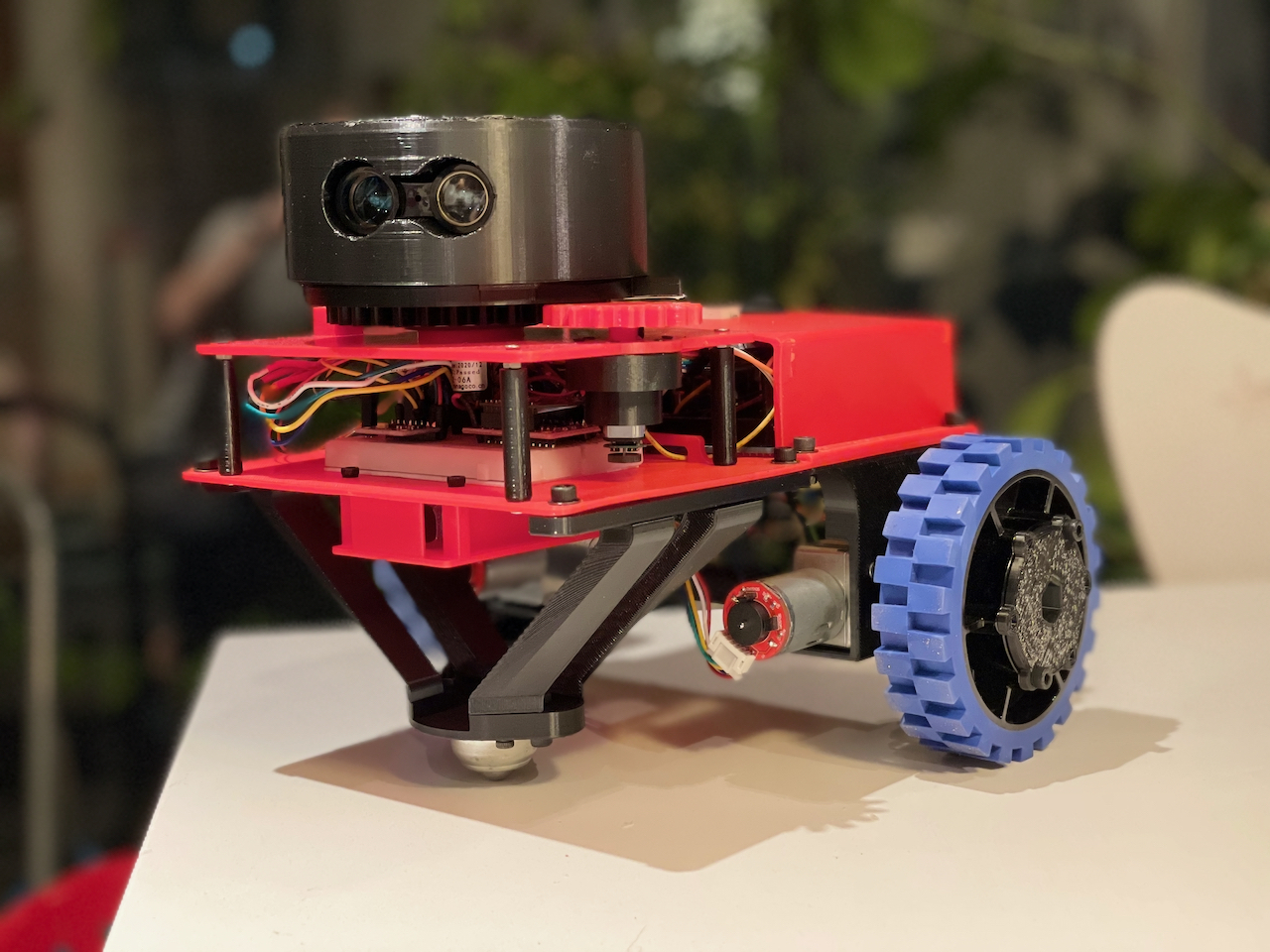
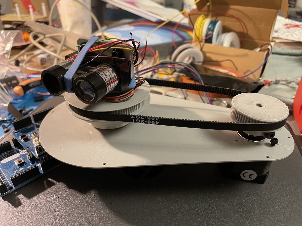
After a few nights of printing and tinkering, I got a successful implementation of the new LIDAR, completely integrated with the Rover!
New design worked really well. Gear based integration with the motor is really smooth, and the sensor placement is perfect. The only issue was having the sensor detect the PLA extrusion. I ended up solving this by gluing a small piece of white printer paper with a thin black line printed on it. QRD1114 detects the switch from white to black on the paper, and nothing else.

Bigger issue was the motor. 6V encoder motors I got from Banggood didn’t have enough torque to drive the gears. I could get them to work at max PWM, but then it could only capture 24 scans per revolution. That’s not enough resolution for mapping.
Thankfully I had another set of encoder motors I had bought on sale. These are tiny 6V motors but they come with a gear reducer attached. I thought this might give me enough torque and I was right. Once I printed a custom holder for the small motor and attached it, it could drive the whole mechanism at 40 PWM range. As a bonus, the motor is four times lighter.
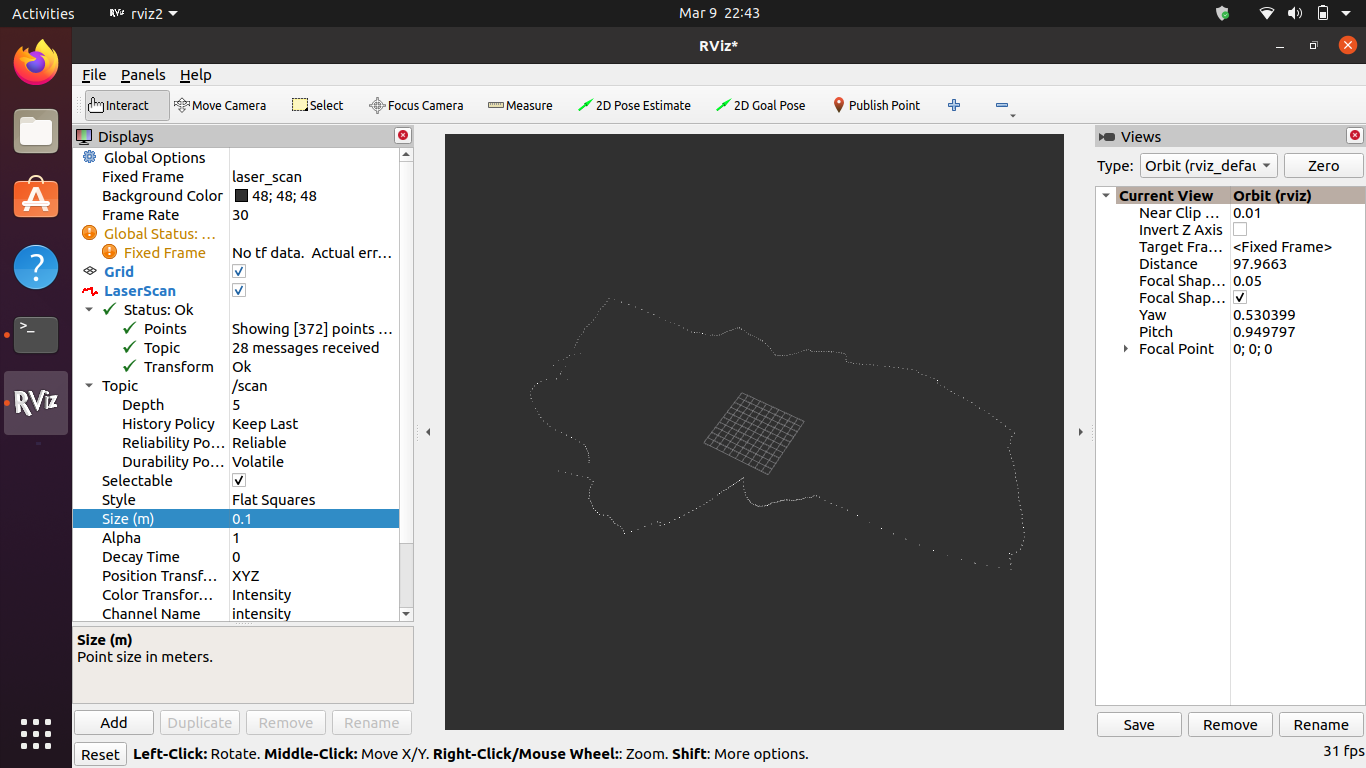
Once I ran this setup, to my delight I got 360 scans per revolution. That’s a one degree resolution per scan and it’s pretty amazing. I can also visualize the laser scan array in Rviz:
Designing Rover v2
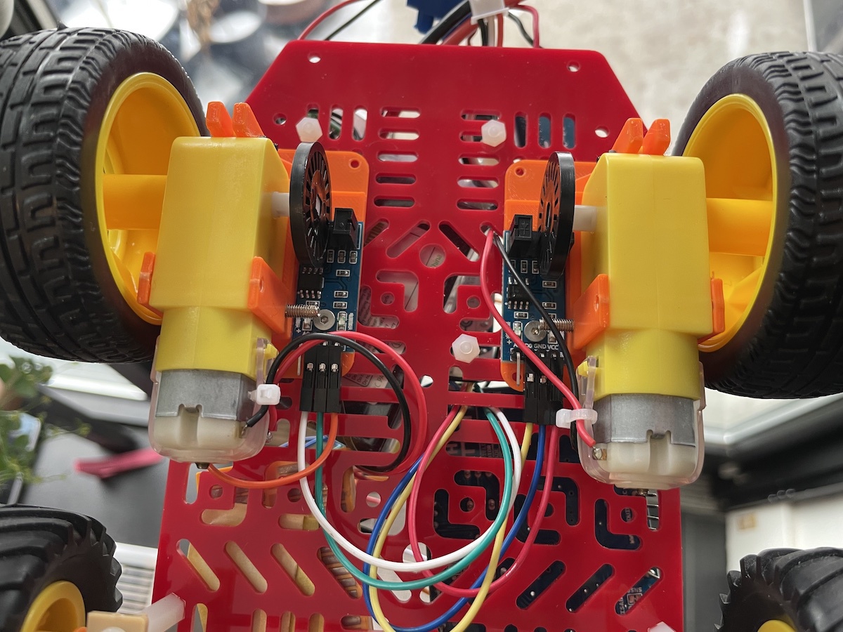
I made some solid progress on the v2 design of the rover during last week and finally assembled an initial test version last night. The difference is incredible. Even with no PID implementation, it drives in an almost perfect straight line. I believe the added weight of the motors and bearings help, but the real star are the new encoded motors.
I found a couple of cheap 12V brushed motors with magnetic encoders on Amazon and designed a custom chassis around them in Fusion 360. Now that I understand the concepts behind Fusion better, I was able to make very quick progress on the design. I kept it as large as possible, within the limitations of the printer bed.
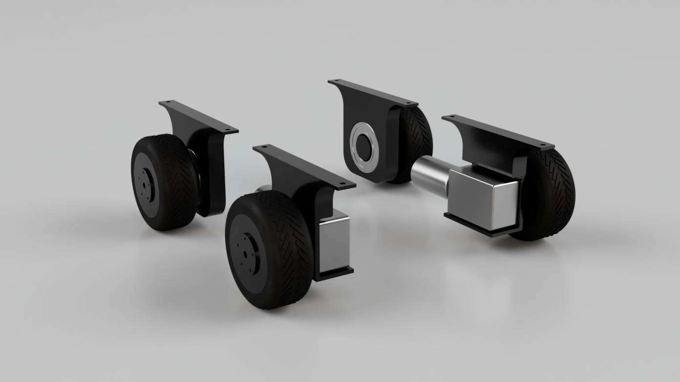
I had a few leftover 42mm bearings from the LIDAR, so I decided to use them for the front wheels. I believe this was a good decision, since it contributes to the base weight considerably, making the vehicle more stable. It also ensures smooth motion on front wheels.
I designed the base level with mounting holes for an Arduino Mega, two L298N motor drivers, and a LiPo holder. There are also mounting holes for a second level, which I am planning to mount the LIDAR on.
Printing went fairly smooth, though I had a small adhesion issue on the large base level. One of the corners lifted during the 9 hour print and warped considerably. On a whim, I decided to use the heat gun on it to try and flatten the piece. To my surprise, it worked quite well. I heated up the corner for 15 seconds, then pressed on it with a heavy wooden box. It’s not perfectly flat but it’s workable.
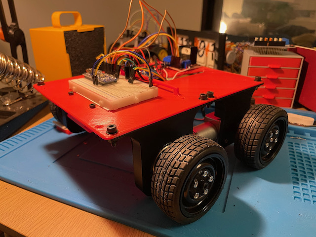
After assembling the whole unit, I took it for a test ride and I was very pleased with the results. Before doing any automated driving, I decided to hook up the XBee module and implement a simple remote control for the rover. I think it’s a good idea to make sure it runs smoothly with manual controls before trying to automate driving. That way I can be sure that there are no mechanical issues before focusing on software.
Encoding DC Motor Steps
Now that I have successfully encoded the stepper motor position for LIDAR, I turned my attention to encoding the DC motors that I am planning to use for running the robot wheels.
There are several good examples of this online, but most use quadratic encoders (DC motors with embedded dual encoders in them, usually magnetic). Unfortunately I don’t have any such motors at hand, and I have many, many DC motors so I am hesitant to buy more.
So after watching this fun little video from Sparkfun, I decided to build my own simple encoder. I already have the optical encoders with disks ready to go. So I designed and printed a motor holder that can hold the gear shaft and encoder disk in place.
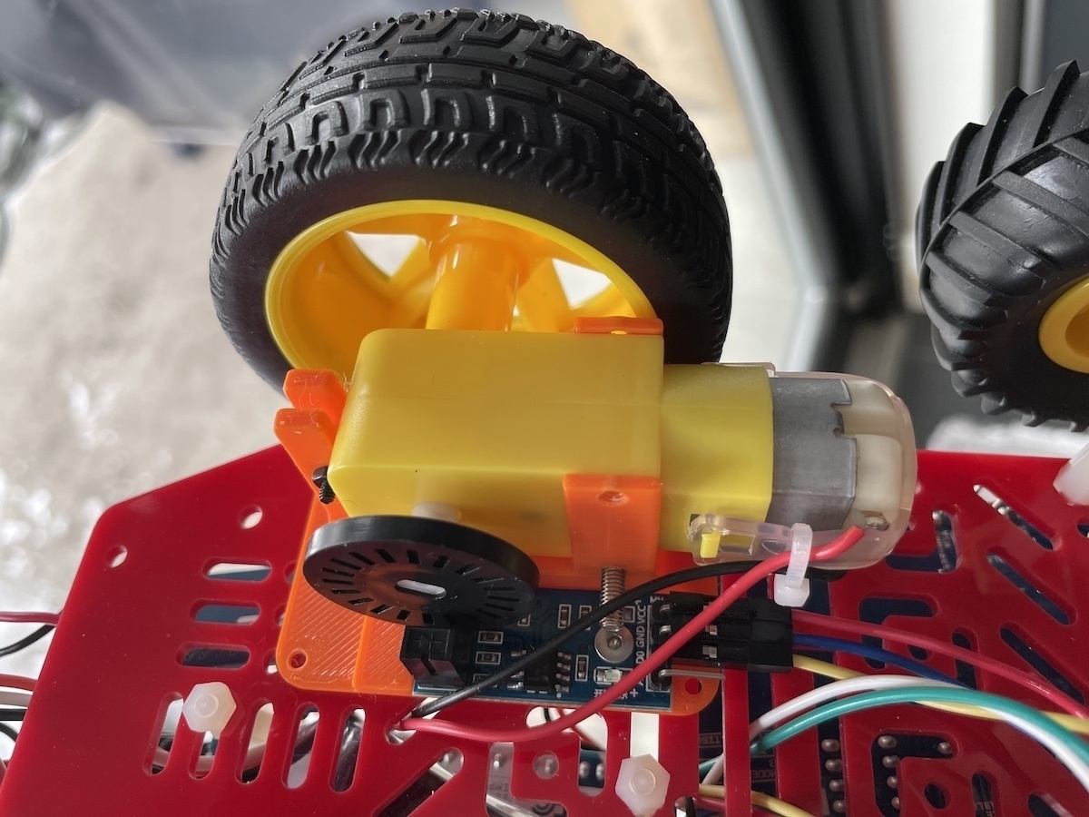
Funny enough, the biggest problem I had was soldering the cables on these flimsy 3V motors. In retrospect using the bigger 6V motors would have been a better idea. I might swap things around once I have a working prototype.
Sparkfun video comes with a handy little code snippet for speeding up and slowing down the two motors so they drive more or less equally. I adapted this for the Arduino Motor Shield and ran a few tests. It seems to be working, but hard to tell without an actual test on the ground.
I will now have to convert everything to run on a LiPo battery so I can autonomously test this on the floor. Objective is to get it to drive straight a specific distance.
Once I have reliable results, I am planning to add coupled Xbee units to be able to remotely control the robot from my laptop.
Stepper Motor Success
After a few days of struggling with stepper motor controls, I finally got everything working reliably last night. There were a lot of learnings along the way, most of them not very well explained on most tutorials I found online.
My problem was essentially that I have a ridiculously powerful set of steppers. I kept referring to them as NEMA-14, but while reading this guide from Adafruit, I learned that NEMA nomenclature doesn’t mean much other than enclosure size.
So I searched the serial number and found the product specs sheet on Pololu. I bought these many years ago so I had no idea what the specs were.
As it turns out, specs are critical when dealing with steppers. You specifically need to know the current requirements per coil (amps per phase and resistance per phase). In my case, it was a fairly high 1A per coil. Problem is, the motor drivers I had couldn’t supply more than 0.6A per coil, and that’s probably why they kept heating up and the motor was so erratic.
Thankfully, I also found some A4983 drivers in a motor drivers box I had in the basement. Perusing the specs showed that they are capable of 2A output! That sounded promising.
After hooking up the driver with the basic setup, I plugged it in to a 24V supply. This was the other learning. Even though the stepper is specced at 2.7V, that doesn’t mean much. They are very power hungry and work more efficiently under higher voltages.
Another thing you have to do with A4983 is to adjust the output current using the potentiometer on board. This can be done using the REF pin and doing a simple calculation. I set it to output roughly 0.8A for starters. This guide on RepRap was excellent for figuring this out.
In any case, I plugged it in and… Nothing happened. I even soldered some pins again since they didn’t look great, and also tried a second driver. But no success. Motor was quiet and there was no movement at all.
This wasn’t too surprising to me because I had tried to make these drivers work back in October for a Halloween project. But this time I was determined. Back to the specs I went.
That’s when I noticed something weird. There was an obscure reference to the board requiring voltage input from the logic controller. Even though I was powering the board and the Arduino separately, A4983 still wanted the 5V from Arduino into the VDD pin. I plugged it in, and the stepper burst into motion as expected!
Next step was testing this alongside the LIDAR. Earlier this week, I had identified the old LIDAR unit I had as a Garmin LIDAR Lite v1. Unfortunately v1 is from 2015 and Garmin dropped support for it a while back (they are on v4 now). They have a well maintained Arduino library but I couldn’t get it to work with v1 unit I have. After much trial and error, I found an Arduino sketch that a kind soul had posted for v1. After some tweaking, I had the Garmin LIDAR Lite v1 delivering consistent results.
Thankfully, making the LIDAR work alongside the stepper was easy. A4983 makes stepper control a breeze. All you have to do send a HIGH to STEP pin and it steps. That’s it, no fuss. With a few lines of code, I had the stepper moving reliably and mapping position data to LIDAR distance measurements.
Of course, the stepper positional data is not reliable and I’m not planning on using it. But if I can couple this with an optical encoder, I should be able to output reliable mapping data.
ZoomBox
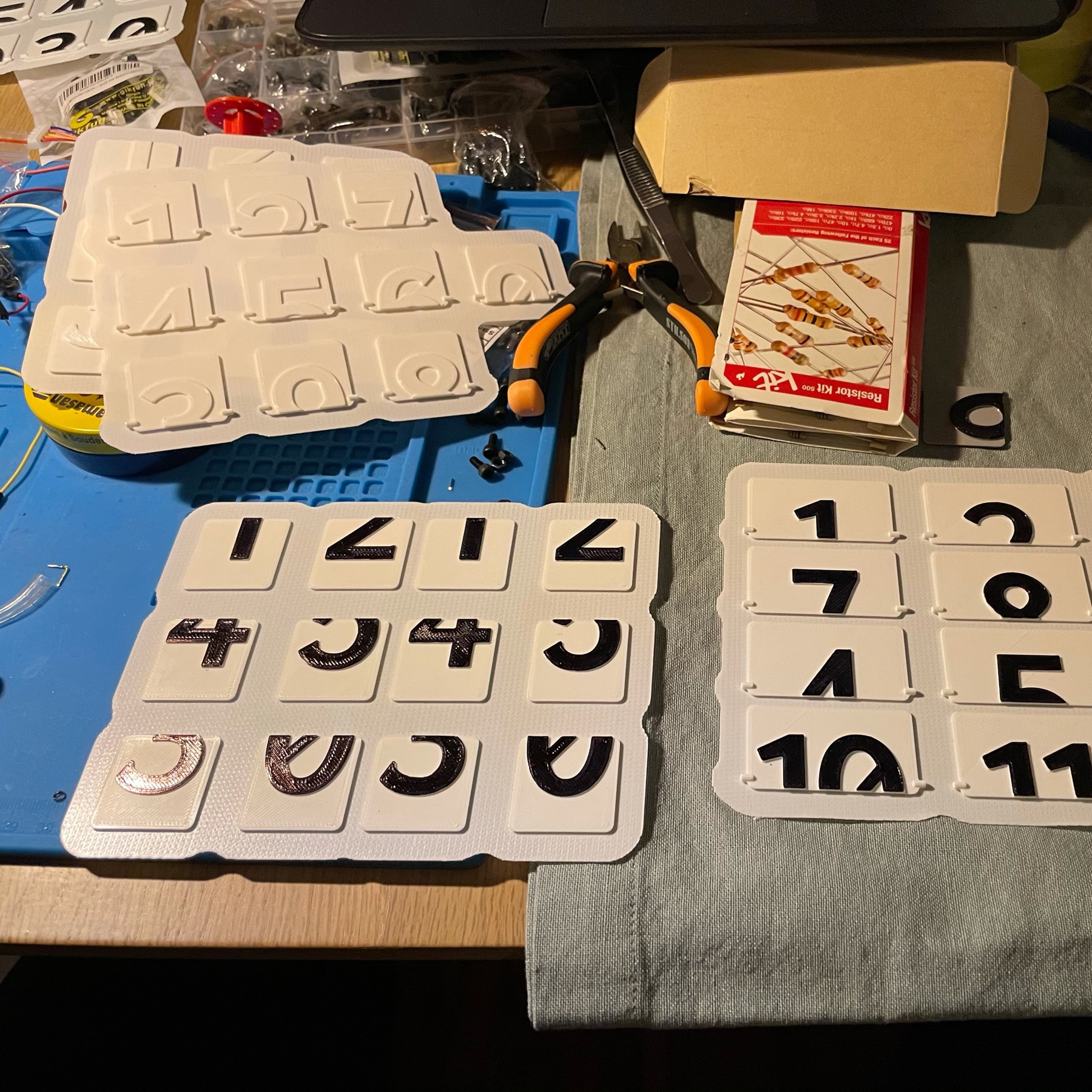
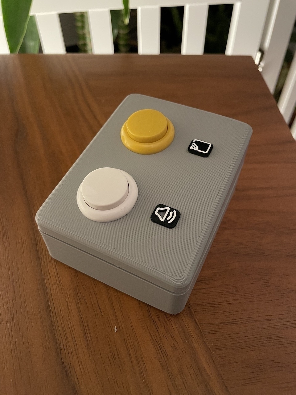
ZoomBox is ready! I designed and printed the top part and fitted the arcade buttons in. I wanted the button icons to be extruded out, which presented a problem. If I extruded them, I couldn’t print the top part upside down. Eventually I decided to print without them and then printed them separately in black filament. Then used a white acrylic pencil to contour the icons. I am pretty happy with the result.
Obviously, using an Arduino UNO for this project is overkill. My research eventually led me to the Arduino Pro Micro, which already has an ATMEGA32u4 in it. This means it’s ready to be used as an HID and all keyboard and mouse control can be done with it.
I will get my hands on some Pro Micros to play with them, but in the meantime this version of the project is a success.
I published all STL models and the Arduino sketch on the ZoomBox Github repo.
Designing with Fusion 360
Despite my initial aversion to it, Autodesk Fusion 360 is truly an amazing tool. The combination of sketching on faces and timeline editing makes it incredibly powerful. Following the great Layer by Layer tutorials form Adafruit I designed a simple case for the ZoomBox. I was able to import the official DXF files from Arduino right into Fusion 360 and map the screw holes exactly.
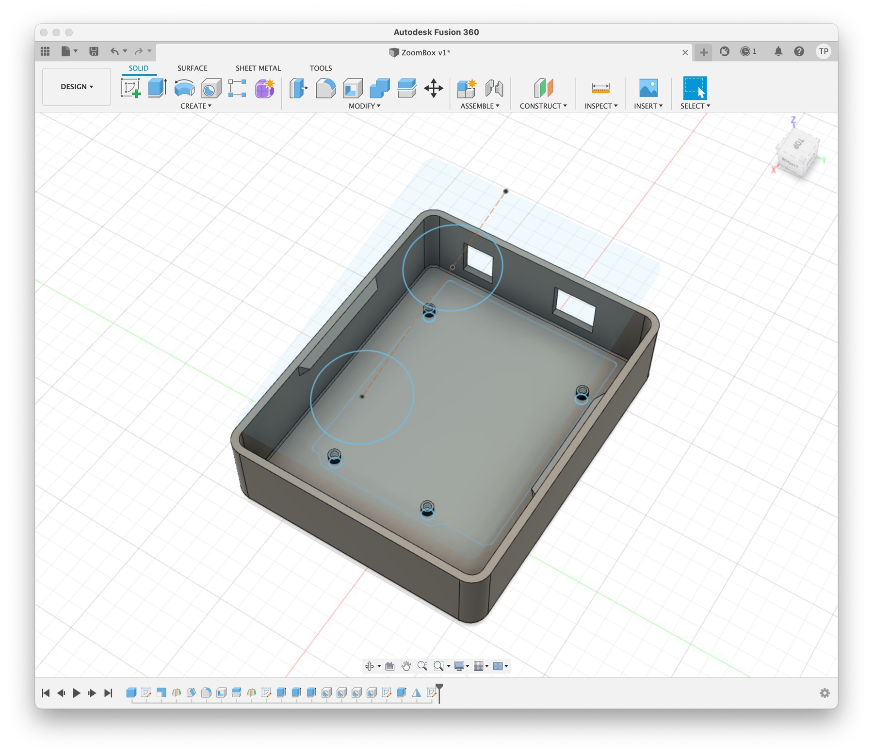
Surprisingly, there was no good information available on component heights. I had to manually measure them. For reference, the USB-A port is 12mm by 11mm and the power jack is 9mm by 11mm. They are respectively 9mm and 4mm inset from the edges of the board. These two drawings were also good references but they didn’t provide all the information I needed:
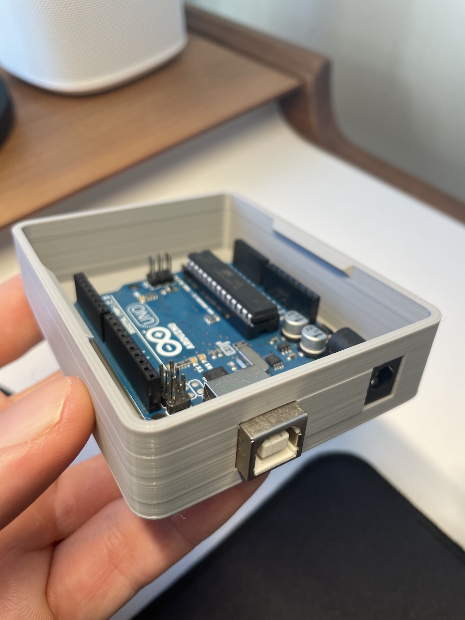
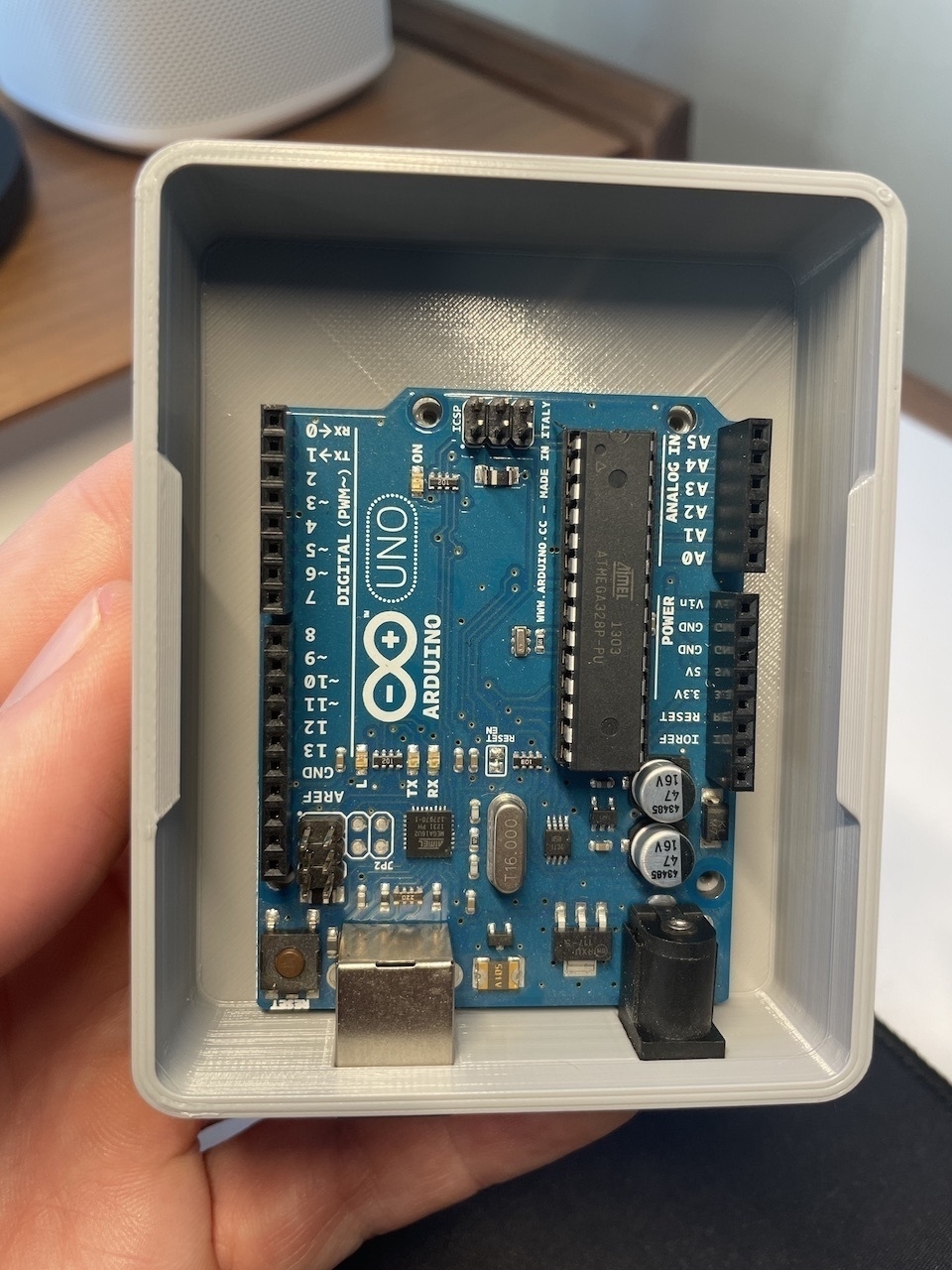
After adding some simple snap fit joints to the bottom part of the box, I sent it to print and went to bed. To my mild surprise, I found a perfectly fitting box in the morning!
Next step: Design the top part with button inserts.
Decided to make the jump and learn Fusion 360. I have been using Blender and as much as I like it, it’s not built for prototype design. I had a visceral reaction to Fusion’s horrible interface but even after a few hours I can see the advantages.
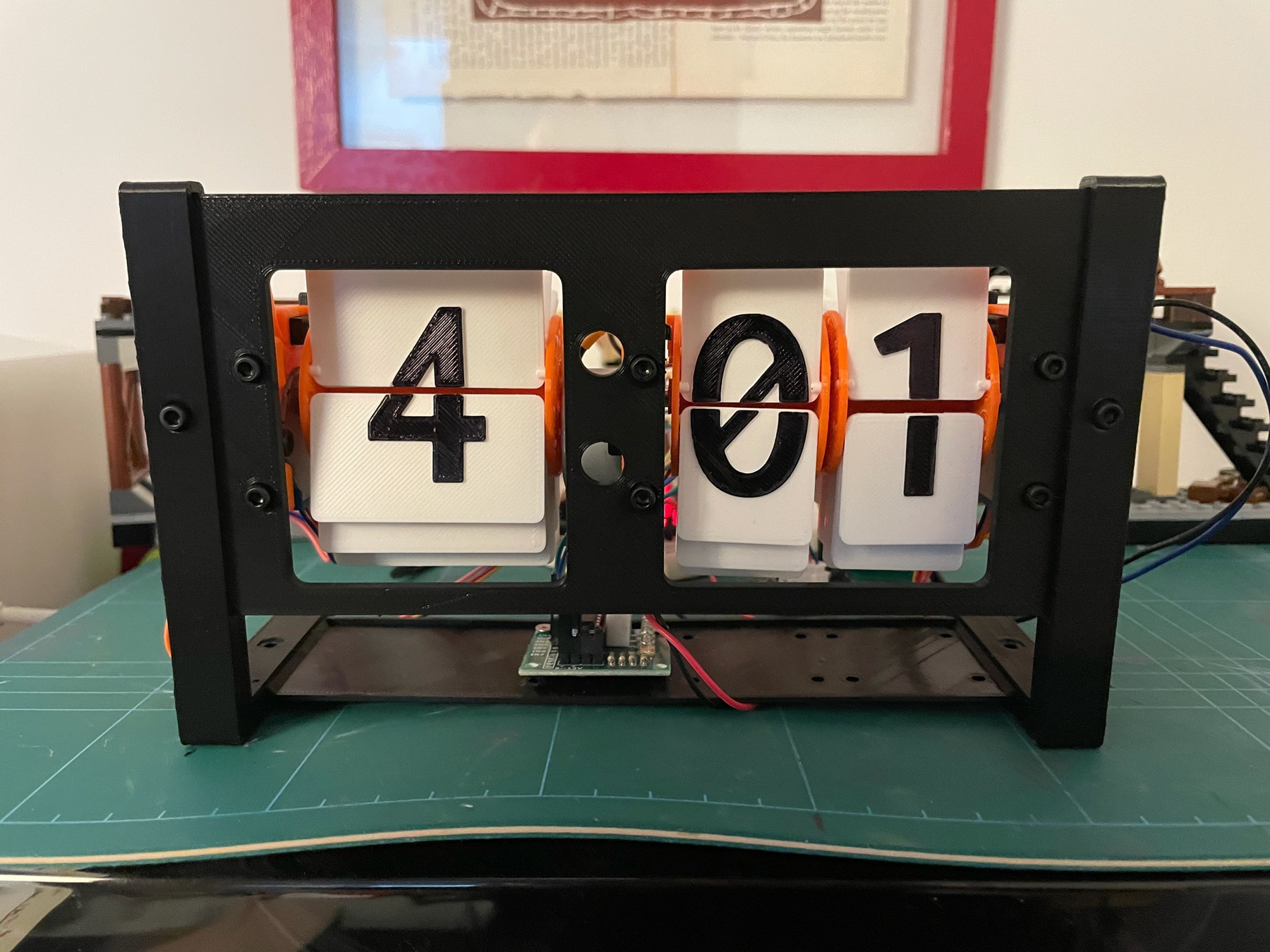
After several minor adjustments, got the first successful version of the flipclock running well. Electronics is a mess that needs to be organized on a PCB, but pretty happy with the results!
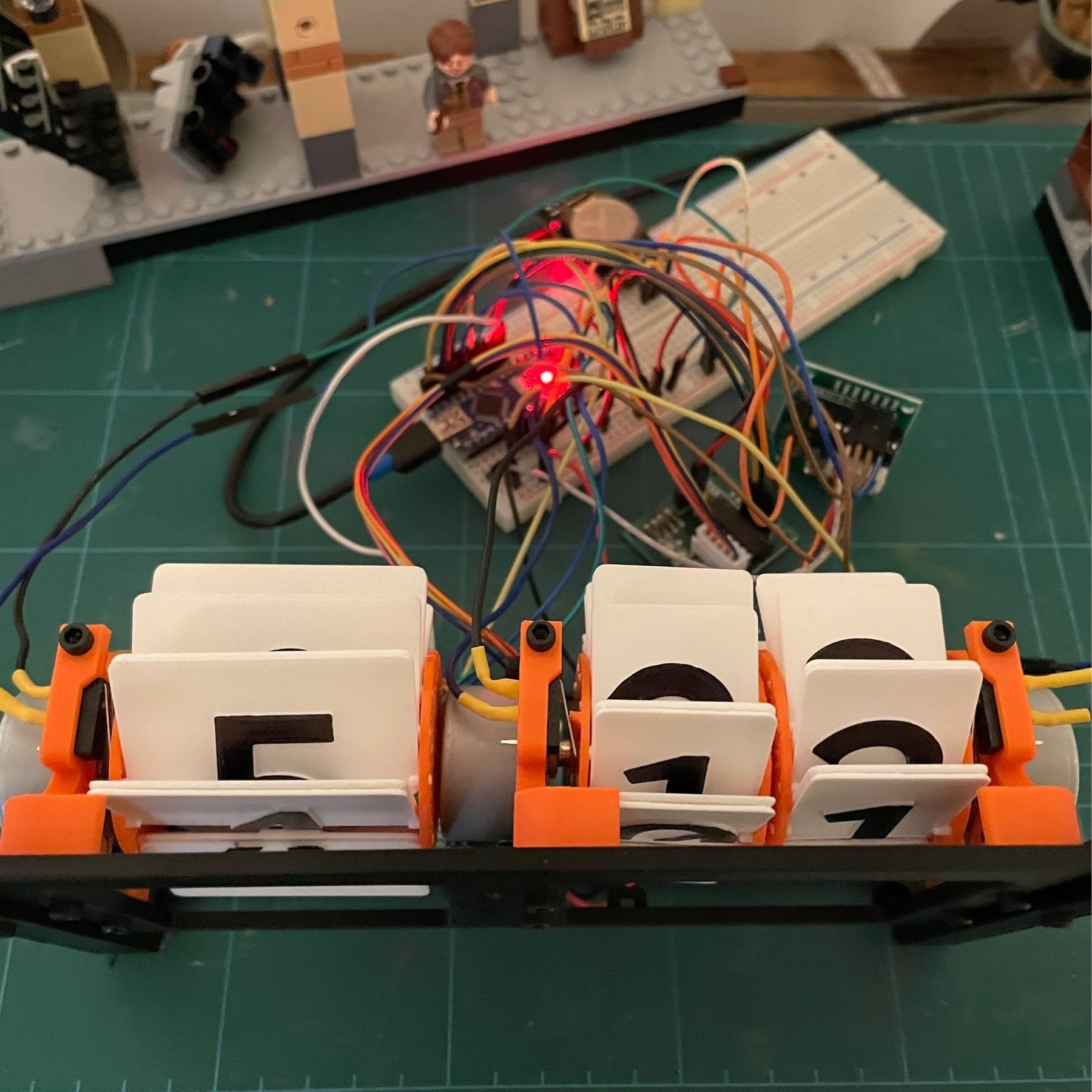
Had some issues with the flipclock. New digits look great, but they didn’t fit in the original spools, since they are thicker. Had to design and print new spools, which meant the motor holder screws got in the way. Hoping to resolve all of this tonight.
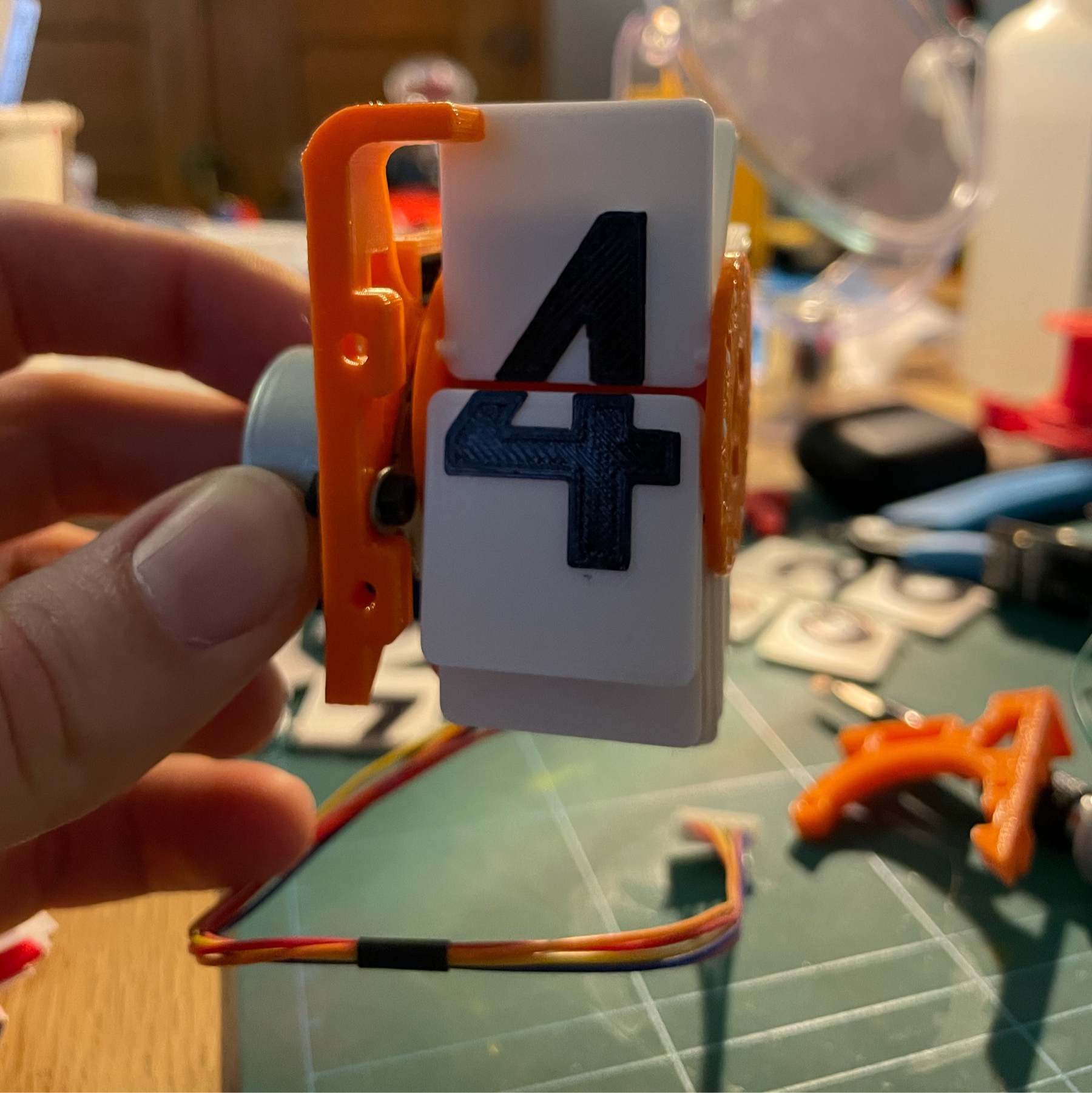
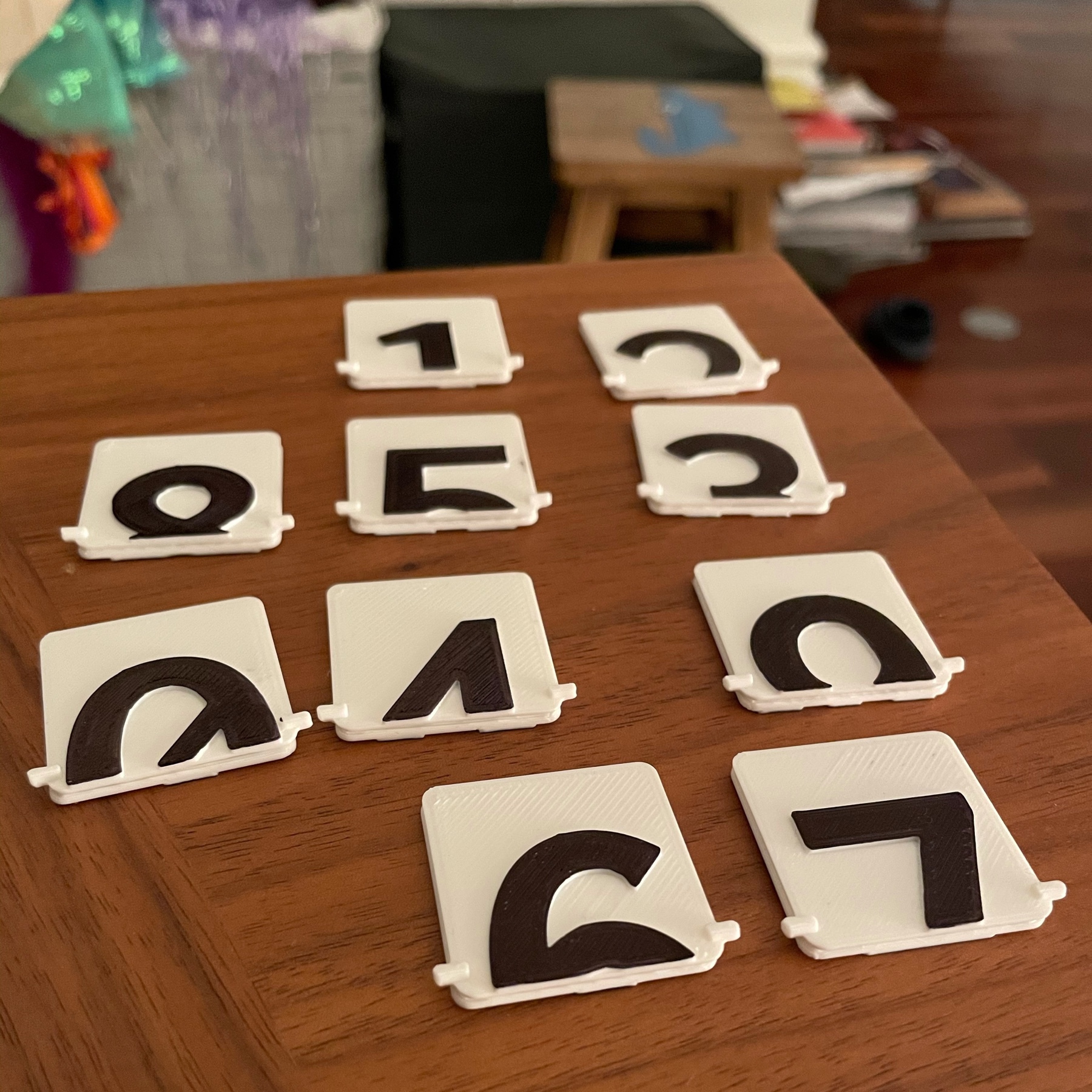
Flipclock digits are assembled! They are looking clean and beautiful. I will be assembling the full device tomorrow evening and hopefully have it functional.
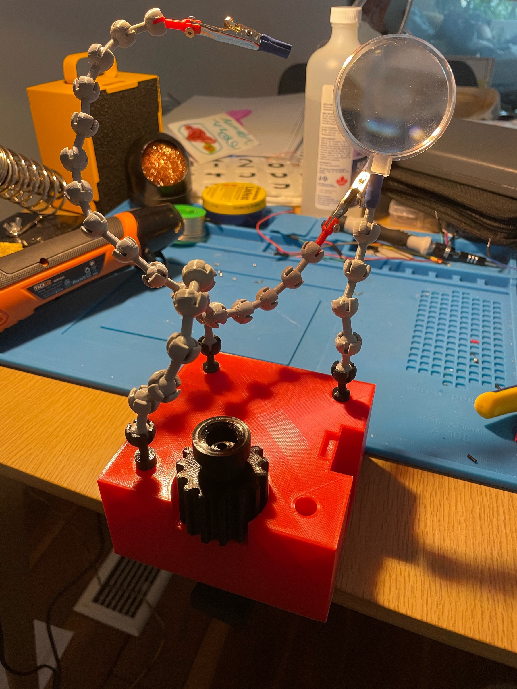
I have some soldering to do this weekend so I decided to improve my setup. After much searching, I found this design on Thingiverse. I modified the base and tips so they fit my alligator clips and can slot in without glue. Pretty happy with the results!
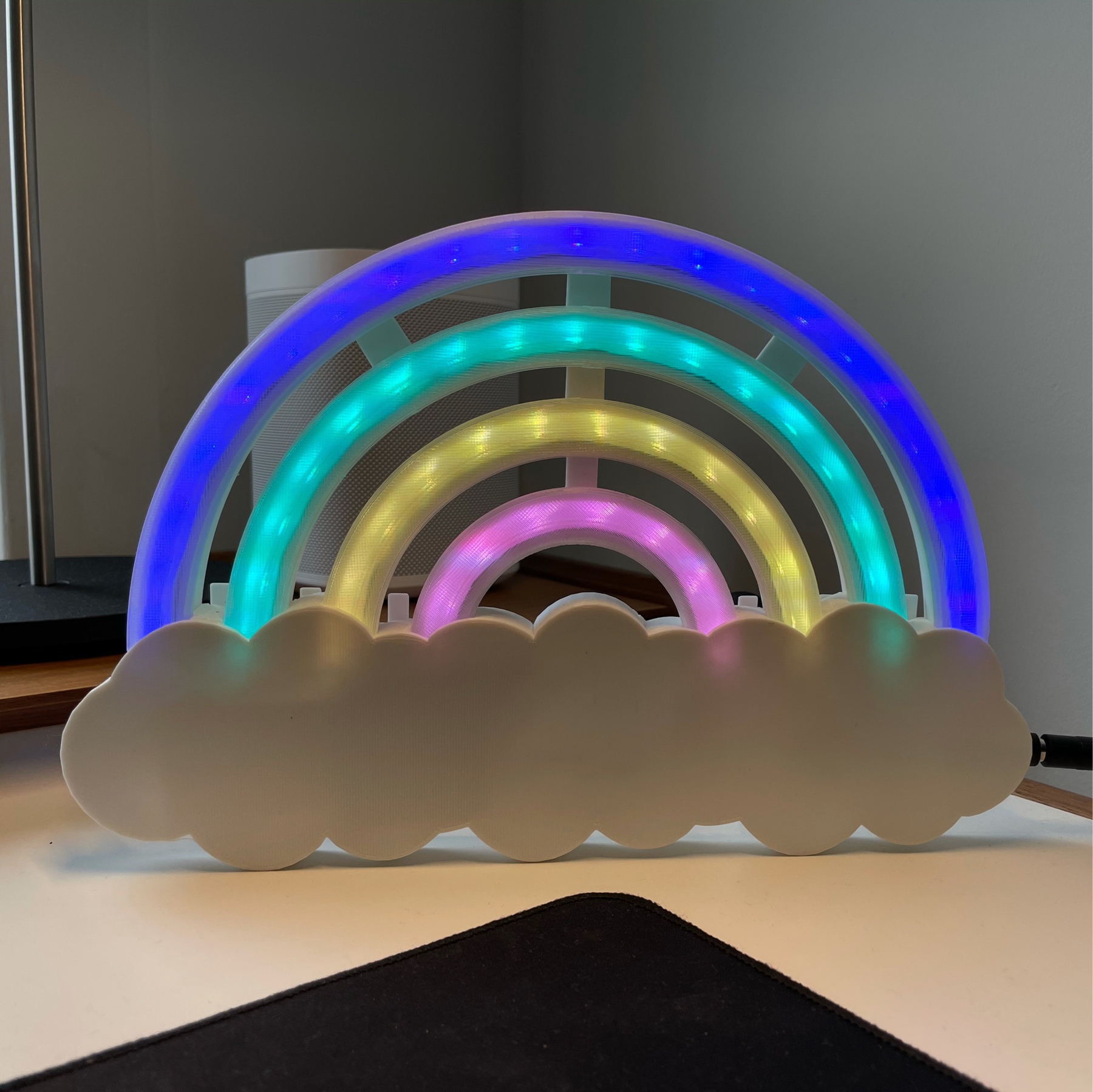
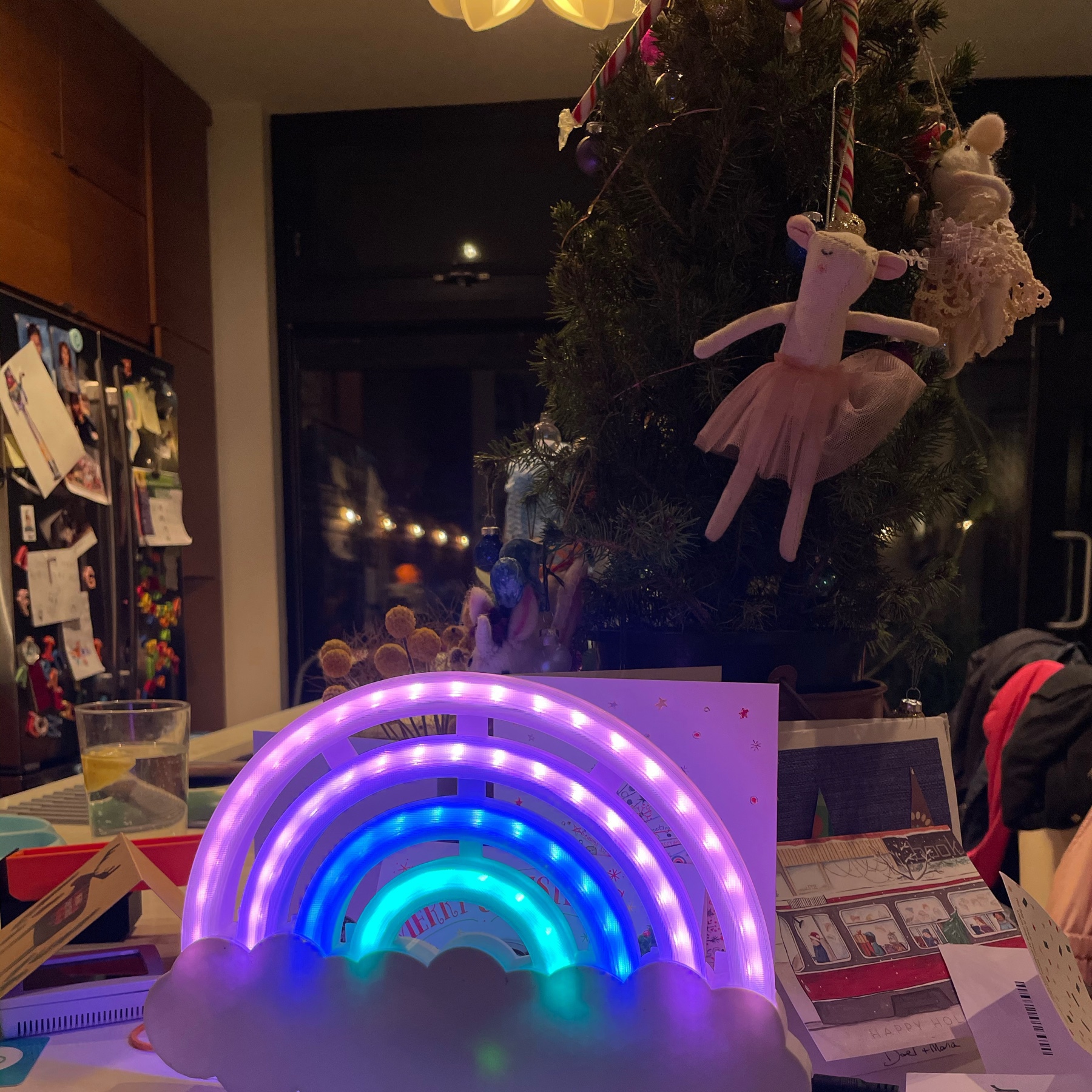
Added some logic to the LED rainbow so it dims slowly over the course of the hour before turning off for the night, and same in the morning. With that, I call this project complete!
Trinket Woes and A Prototyping Lesson
I also managed to get an RTC module soldered on to the LED rainbow I designed for my daughter tonight. Everything was going well until the sketch upload to the Trinket failed.
Apparently Adafruit Trinket has this issue where it’s easy to override the bootloader by mistake. I think it happened because I was using 99% of progmem.
Solution is easy, you just hook up the Trinket to another Arduino and use a little sketch to burn a fresh bootloader. Problem was: Trinket was already soldered on the prototype board!
What followed was two hours of frustrating desoldering and attaching headers.
Lesson learned: Solder headers for core components instead of soldering them directly on prototype boards. You never know when you have to get them out again.
Flipclock prototype is working well. Had to modify the front panel design and reprint, but now it’s moving smoothly. Next step is assembling the embossed digits and minute motors.
This weekend’s project: Building an old school flip clock from scratch. I based the prototype on this awesome project, but ended up redesigning the number cards. New versions are looking great with the embossed digits.