makerdad
LIDAR v2 Design
Now that the Rover v2 base is working and driving well, I am turning my attention to the new LIDAR module. After reconsidering the previous GT2 pulley based design, I decided to redesign it completely on the new Rover base, using a gear based approach.
Reasoning behind using a geared drive is fairly simple: Pulley and timing belt approach didn’t necessarily create a smooth drive mechanism like I had imagined. It also takes up a lot of space and it’s a nightmare to calculate for. Finally, printing GT2 pulleys doesn’t generate very clean results on the 3D printer, which in turn contributes to lack of smoothness.
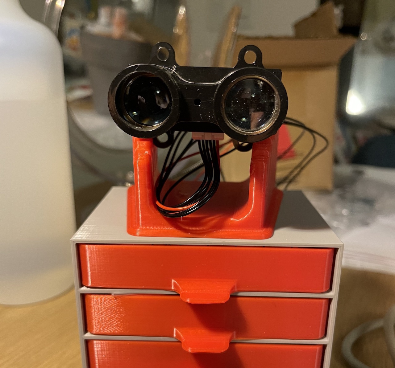
So there are lots of reasons to simplify the design with this version. I kept the bearing the same, but learning from the previous version, made an extrusion that can be detected by the QRD1114, which will be placed conveniently underneath. I also have a nice little lid for the LIDAR.
After a few nights of printing and tinkering, I got a successful implementation of the new LIDAR, completely integrated with the Rover!
New design worked really well. Gear based integration with the motor is really smooth, and the sensor placement is perfect. The only issue was having the sensor detect the PLA extrusion. I ended up solving this by gluing a small piece of white printer paper with a thin black line printed on it. QRD1114 detects the switch from white to black on the paper, and nothing else.

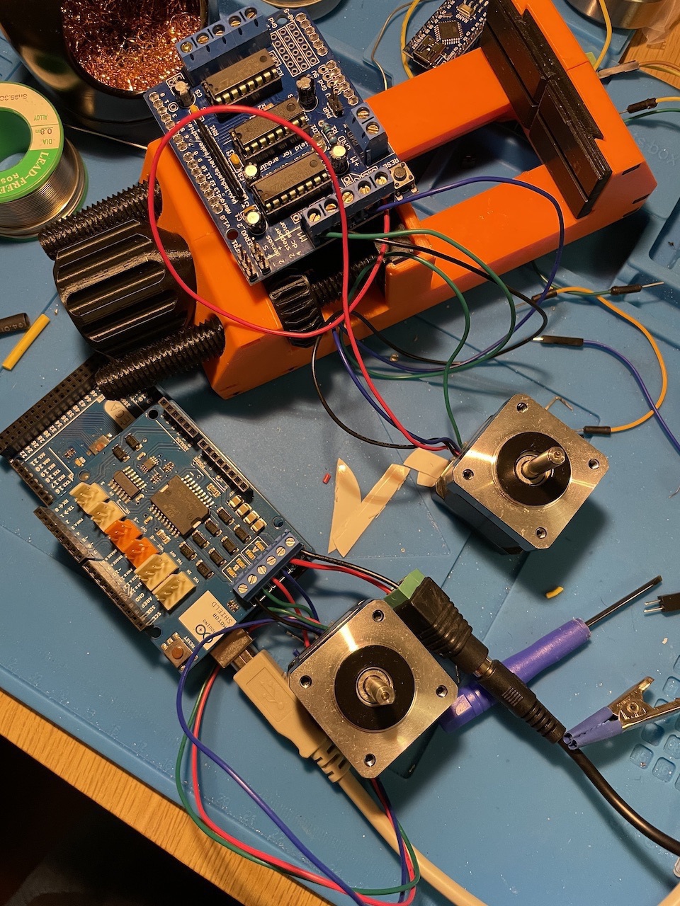
Bigger issue was the motor. 6V encoder motors I got from Banggood didn’t have enough torque to drive the gears. I could get them to work at max PWM, but then it could only capture 24 scans per revolution. That’s not enough resolution for mapping.
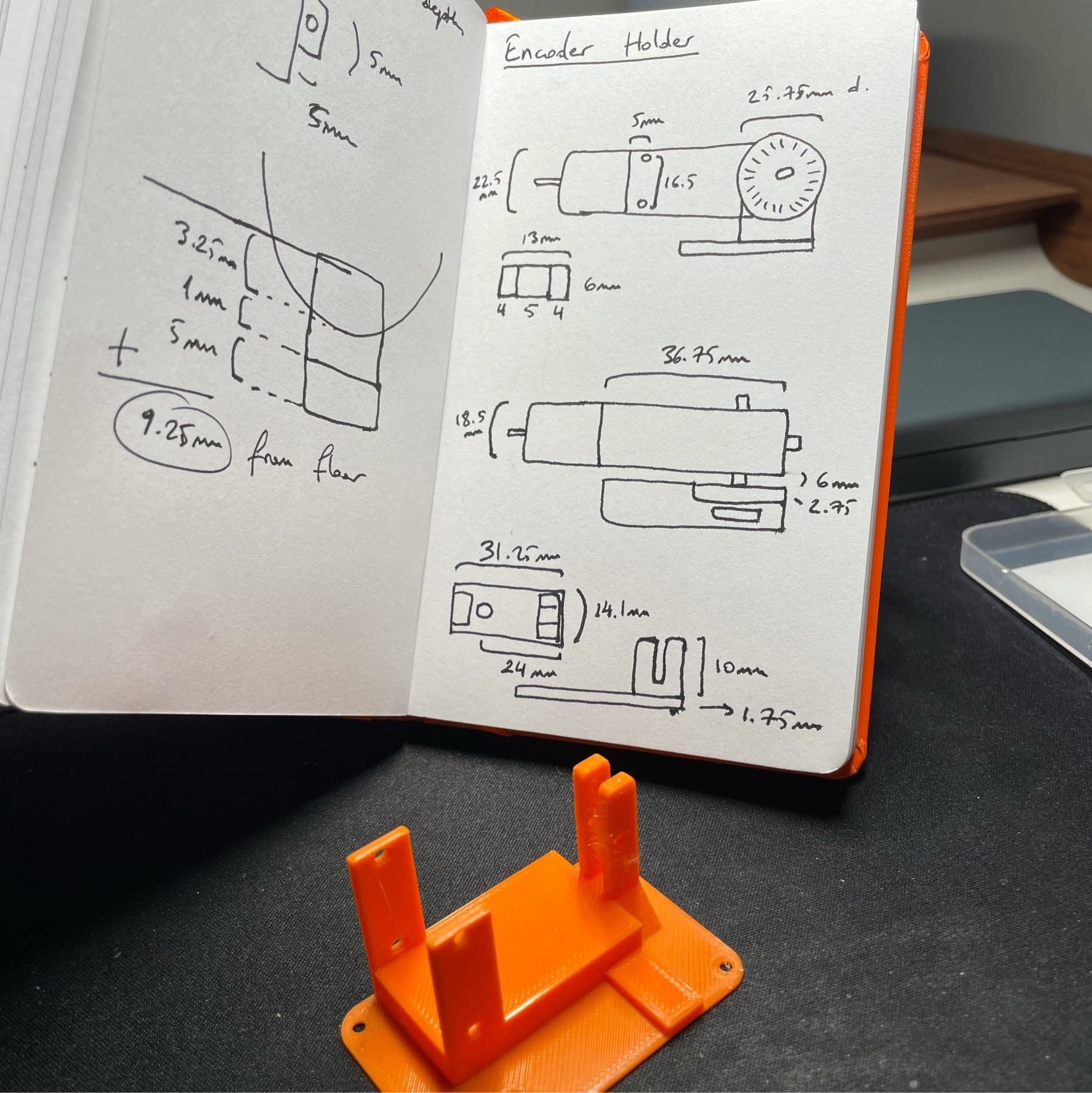
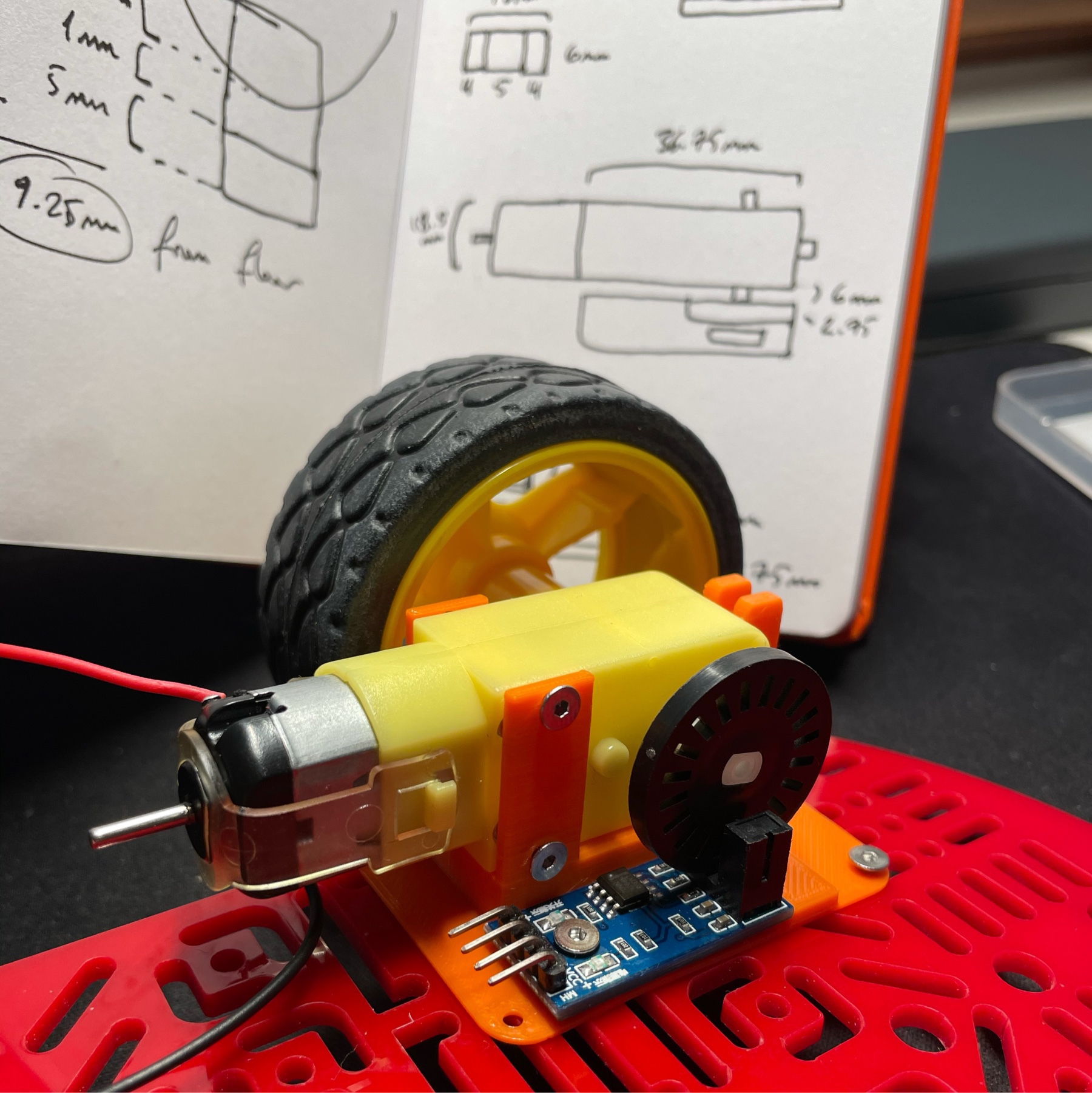
Thankfully I had another set of encoder motors I had bought on sale. These are tiny 6V motors but they come with a gear reducer attached. I thought this might give me enough torque and I was right. Once I printed a custom holder for the small motor and attached it, it could drive the whole mechanism at 40 PWM range. As a bonus, the motor is four times lighter.
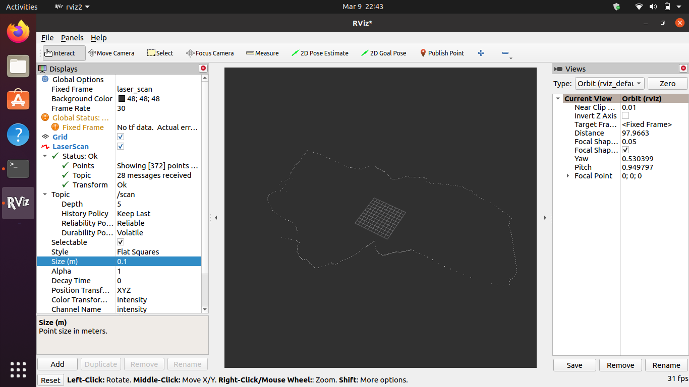
Once I ran this setup, to my delight I got 360 scans per revolution. That’s a one degree resolution per scan and it’s pretty amazing. I can also visualize the laser scan array in Rviz:
Driving Rover with an Xbox Controller
Before jumping to the PID implementation and eventually autonomous driving, I wanted to make sure that the Rover v2 could drive and turn with stability. I could have done a simple keyboard implementation but I really wanted to integrate an old Xbox controller I had lying around.
What I have seems to be an Xbox One controller and it connected to my Mac over Bluetooth with no issues. After some research, I found out that pygame is actually the best way to work with these game pads.
I had never used pygame before but it felt very natural. It has a great abstraction layer for the various controls on the gamepad so I could easily extract axis data from joysticks relatively easily:
import pygame

pygame.init()
controller = pygame.joystick.Joystick(0)
controller.init()

while True:
    left_power = controller.get_axis(1)
    right_power = controller.get_axis(3)
    left_speed = int(abs(left_power) * MAX_POWER)
    right_speed = int(abs(right_power) * MAX_POWER)
I then coupled this with the previous XBee implementation I had done and hooked it up with pyserial. To Python, XBee looks like just another USB port and thanks to the magic XBees all the remote control part is taken care of.
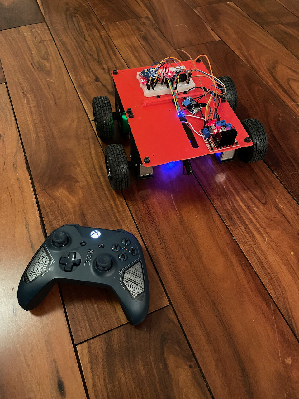
After some tinkering, I had a sweet little Python script that got the control values from the Xbox controller and passed them on to the Arduino on the rover. Here it is in action:
Overall I’m very happy with this. I think the crappy tires are causing issues with traction though. I will have to swap them out or print new ones using the new direct drive extruder I got.
Next step: PID implementation, two way data transfer, and eventually ROS integration for control. I also need to redesign the LIDAR piece to fit on the rover. Instead of pulleys, I’m planning to do a gear based implementation.
PID Tuning Experiments
I spent the last few days experimenting with PID algorithms and tuning parameters for straight driving using only motor encoders. There were tons of learnings along the way, and I’ll try to summarize them in this post.
First off: After a lot of frustration, I realized that there was something wrong with my motor setup. Whatever I did, there was a huge discrepancy between the two geared motors. They are identical models with the same 48:1 gear boxes. However some simple encoder analysis showed that left motor was going at around 60% the speed of the right one.
I eventually tracked the issue down to the buck converter. I was limiting LiPo voltage down to 6V using a cheap buck converter. Checking the specs, I realized that the converter was only capable of 1A output. Motors were probably trying to draw more current than 1A, since the H-bridge can provide 2A per channel!
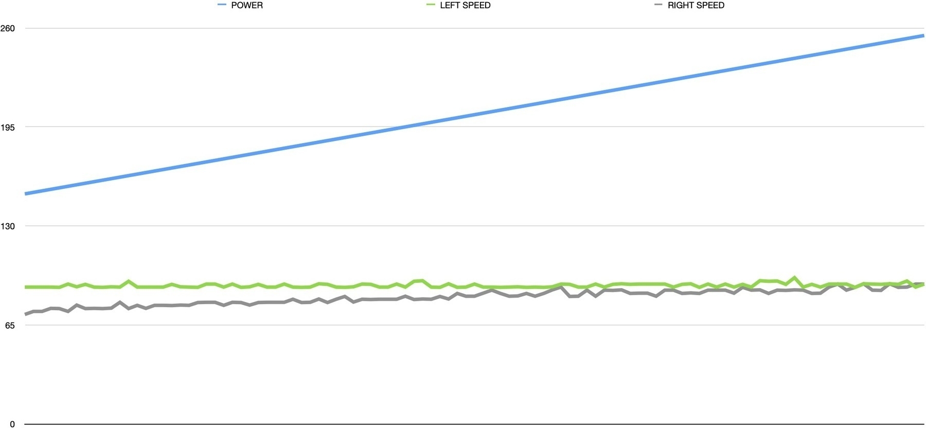
For a quick experiment, I plugged the LiPo straight into the H-bridge and the motors roared! 7.4V is probably a bit too much for them, but the speed discrepancy also disappeared. I also learned the importance of graphing data. Here is a simple speed calculator that increases motor speed every 500ms and logs the speed from each encoder:
int motorPower = 100;
int motorBias = 0;
double leftSpeed, rightSpeed = 0.0;
long lastCheckTime, nowTime = 0;
long lastLeftTurns, lastRightTurns = 0;
uint32_t leftDelta, rightDelta , timeDelta = 0;

lastCheckTime = millis();

while (motorPower <= 255 - motorBias) {
    analogWrite(PWM_A, motorPower - motorBias);
    analogWrite(PWM_B, motorPower + motorBias);

    delay(500);

    nowTime = millis();
    leftDelta = leftTurns - lastLeftTurns;
    rightDelta = rightTurns - lastRightTurns;
    timeDelta = nowTime - lastCheckTime;

    leftSpeed = (double)leftDelta / (double)timeDelta * 1000.0;
    rightSpeed = (double)rightDelta / (double)timeDelta * 1000.0;

    lastCheckTime = nowTime;
    lastLeftTurns = leftTurns;
    lastRightTurns = rightTurns;

    Serial.print(motorPower);
    Serial.print(F("\t"));
    Serial.print(leftSpeed);
    Serial.print(F("\t"));
    Serial.print(rightSpeed);
    Serial.println();

    motorPower += 1;
}
As a bonus, this outputs tabulated data into the serial monitor, which you can easily paste into a spreadsheet for charting. Here you can see the increasing motor power and the speed discrepancy actually disappearing as the motors get closer to full power:
Now that I was more confident with the power requirements and mechanics working well, I went back to the PID implementation. I had experimented with several methods before and upon further reflection, decided that a single PID controller that optimizes for minimum difference between motor speeds is the way to go:
double PID_setpoint = 0.0; double PID_output = 0.0; double PID_input = 0.0; const double Kp = 5.0, Ki = 0.01, Kd = 0.1; long nowTime;
PID PIDController(&PID_input, &PID_output, &PID_setpoint, Kp, Ki, Kd, DIRECT);

...

PID_input = (double)leftTurns - (double)rightTurns;

PIDController.Compute();

if (PID_output < 0.0) {
  leftMotorDirection = (PID_output > -50.0);
  rightMotorDirection = true;

  digitalWrite(DIR_A, rightMotorDirection ? LOW : HIGH);
  digitalWrite(DIR_B, leftMotorDirection ? HIGH : LOW);

  outputLeft = (POWER_OFFSET / 2) + (PID_output / 2);
  outputRight = (POWER_OFFSET / 2) - (PID_output / 2);
} else if (PID_output > 0.0) {
  leftMotorDirection = true;
  rightMotorDirection = (PID_output < 50.0);

  digitalWrite(DIR_A, rightMotorDirection ? LOW : HIGH);
  digitalWrite(DIR_B, leftMotorDirection ? HIGH : LOW);

  outputRight = (POWER_OFFSET / 2) - (PID_output / 2);
  outputLeft = (POWER_OFFSET / 2) + (PID_output / 2);
}
In this sample, I have the PID_setpoint targeted at zero. This is because we are calculating based on the delta between left and right motor encoder values. If they were going at exactly the same speed, the values would both be zero, so that’s what the PID is trying to achieve.
Things get a bit gnarly in the PID_output analysis, since we need to convert this single value into a meaningful output for the two motors. To complicate matters, motors can go forwards and backwards, which needs to be extracted from the same parameter.
This is when I finally got to the point of tuning the PID algorithm. Some research showed that a simple approach is to do the following:
- Set all values (Kp, Ki and Kd) to zero
- Increase Kp until the response is steady oscillation (in my case, motors getting faster and slower back and forth)
- Increase Kd until oscillations go away
- Repeat these steps until Kd increase does not stop the oscillations
- Once Kp and Kd are stable, increase Ki until it gets you to the setpoint with the number of oscillations desired
I got the implementation to a point where it steadily oscillates between one motor and the other, which was really promising. Having played with this setup for a couple of weeks though, I am starting to feel that I am causing myself more trouble than it’s worth by trying to get a stable implementation using cheap hardware. The 3V toy motors I am using are very unstable, and the lack of PWM range on them (due to lack of torque) means the PID doesn’t have a lot of room to play with.
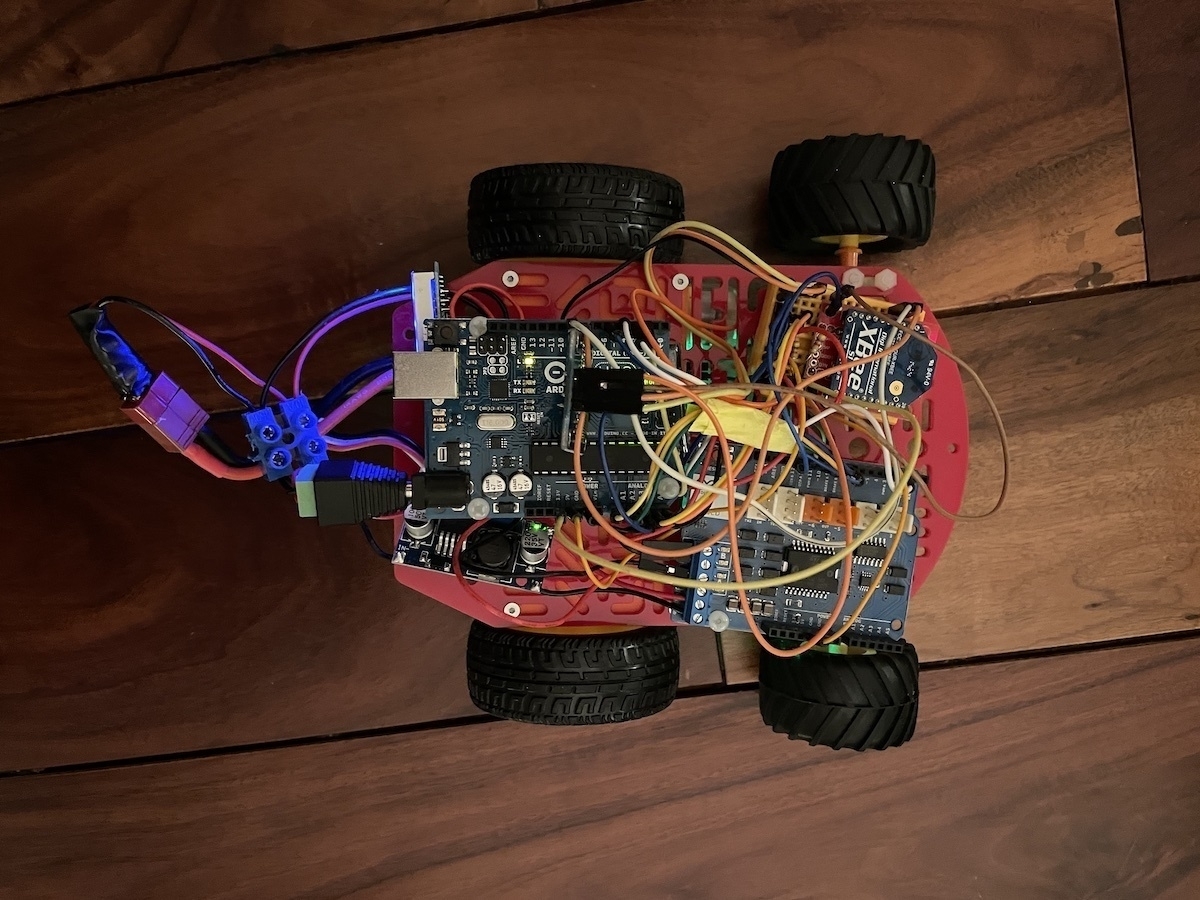
After thinking this through a bit more, I decided that moving to a fresh rover platform, using the learnings from v1, would be best. I found some 12V geared, encoded motors online and ordered them. I am going to begin designing a custom rover on Fusion 360 and see where that gets me. Stay tuned!
Driving Straight for Real Using PID
After implementing the simple straight driving sample for the rover, and integrating the XBee wireless protocol, it was time to test things out. I installed the new gearboxes (they came with motors installed and cables soldered, yay!) and did a test run. However, the first issue I ran into after switching to the battery setup was the OLED screen not starting up. I lost a bit of time on this, because the screen was actually working well when I connected the Arduino to the computer.
OLED screen uses I2C, so I figured it was an issue with the I2C discovery step and spent some time debugging it to no avail. Then I realized that the screen only worked when the serial monitor was turned on. This led me to suspect the software serial implementation, and I was right.
I was using SoftwareSerial to run the XBee serial communication module. Some research showed that SoftwareSerial has some serious performance issues. An alternative suggested was AltSoftSerial, so I gave it a try and magically things started working again! Lesson learned. One note for future though: AltSoftSerial is very well optimized, but disables PWM on Pin 10.
Now that everything was running smoothly, I ran my first test on the ground. Results were better, but not great. Rover was still swerving quite a bit to the left. I suspected some of this was mechanical, since I had a caster at the front and it’s not the best solution for making sure the robot is moving on a straight line. So I reworked the front into a two wheel setup. This helped somewhat and definitely removed a lot of friction, but the swerve was still there.
I also suspected that the simplistic motor speed modulation script I took from the Sparkfun sample didn’t work great. So I did some research into how this is achieved and came across a concept called a PID controller. A proportional–integral–derivative controller is apparently a logic loop that keeps adjusting an output value based on an input and an expected input value. Algorithm itself is not that complicated, but there is also a great Arduino library for implementing it that simplifies things significantly.
That said, it took me a bit of time to understand how to implement PID into my control system. PID itself is agnostic to the way it’s implemented, all it primarily cares about is the three values: input, output and setpoint. Then it runs on a specific time cycle, giving back output values.
Output is easy to understand, it’s essentially the PWM value that’s pushed out to the motor so it determines the motor speed. Input and Setpoint obviously need to be of the same unit type. In my case, they need to relate to the encoder values. What I was doing before was simply checking how close the two motor encoder values were, and varying the speed accordingly. That approach doesn’t really work with the PID controller.
Solution was to separate out the two motors completely. Instead of doing a comparative analysis, each motor needs to have its own PID controller, checking its encoder output against a preset expected value (hence the term “setpoint”). So I ended up calculating the amount of encoder clicks that are expected over a specific period of time and converting that to a time based frequency. Then I compared that to an expected frequency.
As an example, I could say that I would run the PID controller calculation every 100ms, and say that the expected encoder click change every 100ms is 50 clicks. Then I pass the actual encoder click delta in the same timeframe and the PID controller compares this and makes a decision as to how much power should be outputted to the motor (as PWM).
This article on element14 was very helpful. There is also a Zumo bot project I found that was very useful for understanding the concepts, however I didn’t end up using the implementation since the Arduino PID Library provided much better abstraction.
Of course, the actual PID implementation is much more complicated than this. There are three additional parameters: proportional, integral and derivative attributes. These are used to “tune” the PID algorithm and have it output expected results. Unfortunately tuning PID seems to be a bit of a black magic and I will have to spend some time on this.
Good news is that the initial implementation is working really well after some tinkering with it. Here is a video of it in action:
Next step is to add rotation to this flow. And then I will work on a dead reckoning implementation to have it move reliably on a specific path.
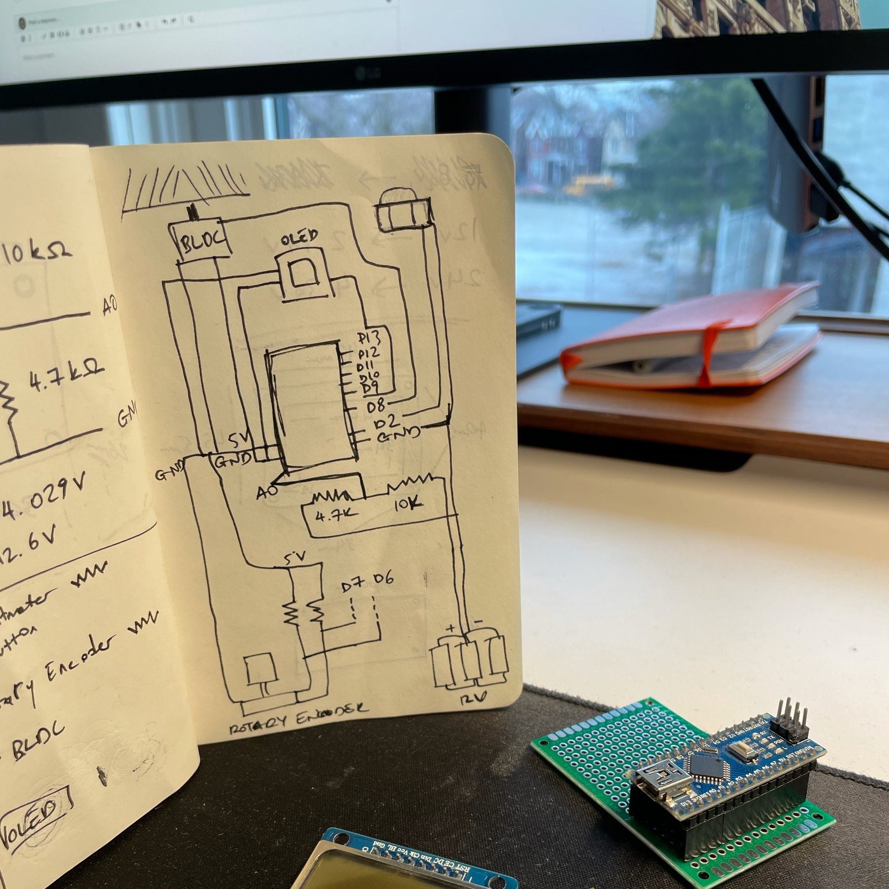
XBee Protocol Design
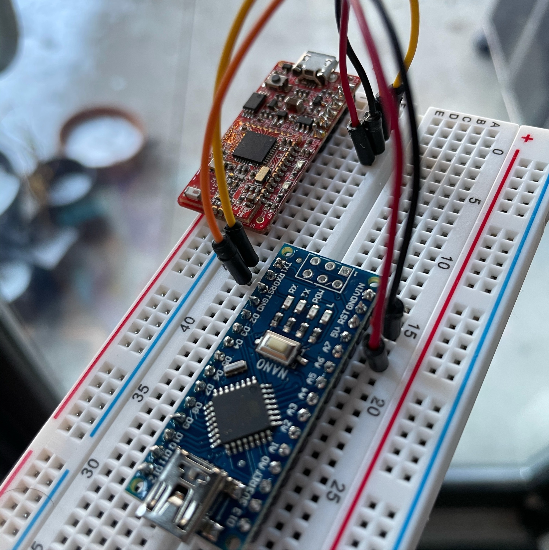
One of the goals of the self driving rover project has always been to have it controlled by a base “brain” unit that does the actual analysis and motion control. I have a few XBee S1 units I had purchased a long time ago and I wanted to put them to good use for this.
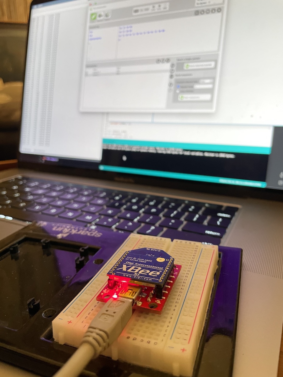
XBees are quite versatile but notoriously hard to configure. There are tons of configuration options available and the XCTU software is not the most friendly.
I started out by plugging both XBees to a USB FTDI board and launched XCTU to make sure they are properly visible. After finding them, I reset them to factory settings in case some weird config is lurking in there. Then I configured one as the controller and the other as the end unit. I set the matching address attributes to make sure they could auto-discover each other. There are tons of good articles on this part. This one from Sparkfun and this beginner’s guide to XBee on Atomic Object were very helpful.
Once configured, I hooked up the end unit one to the Arduino. It’s a simple connection, and thanks to the SoftwareSerial library, you don’t have to use the hardware RX/TX ports. Actually it’s recommended that you use this method, since RX/TX might interfere with USB serial communications.
Then I uploaded a very simple sketch on the Arduino. It simply prints out every received byte from the XBee:
while (XBee.available()) {
    char value = XBee.read();

    Serial.println(value);
}
I then went into terminal mode on XCTU and started typing random commands. Output immediately came back through the Arduino to the serial monitor. Things were looking good.
Next step was designing a simple protocol for sending a command and a value. My thinking was that I could get away with three commands:
- Forwards:
F - Backwards:
B - Rotate:
R
Then I could append the value to this. For instance F100 would move 100cm forwards.
Reading from XBee is no different than any other serial interface. However I wanted to ensure full commands were being read without having to enforce a command length. I decided to use byte 0x0D as the end delimiter. This seems to be the carriage return character and keeps the terminal tidy as well (since there is one command per line).
Implementation required me to refresh my C knowledge a bit. I had to figure out how to properly convert an array of char values into an integer and then how to reset the values in that array (memset to the rescue).
Here is the relevant implementation:
const char COMMAND_FORWARDS = 0x46;
const char COMMAND_BACKWARDS = 0x42;
const char COMMAND_ROTATE = 0x52;
const char COMMAND_END = 0x0D;

char command = 0x00;
char payload[5] = {};
uint8_t payload_index = 0;

while (XBee.available()) {
    char value = XBee.read();

    if (value == COMMAND_END) {
      int value = atoi((char *)payload);

      Serial.println(command);
      Serial.println(value);

      display.clearDisplay();
      display.setCursor(0, 0);

      if (command == COMMAND_FORWARDS) {
        display.println(F("Forwards:"));
      } else if (command == COMMAND_BACKWARDS) {
        display.println(F("Backwards:"));
      } else if (command == COMMAND_ROTATE) {
        display.println(F("Rotate:"));
      }

      display.println(value);
      display.display();

      payload_index = 0;
      command = 0x00;

      memset(payload, 0, sizeof(payload));
    } else if (payload_index == 0) {
      command = value;
      payload_index++;
    } else {
      payload[payload_index - 1] = value;
      payload_index++;
    }
}
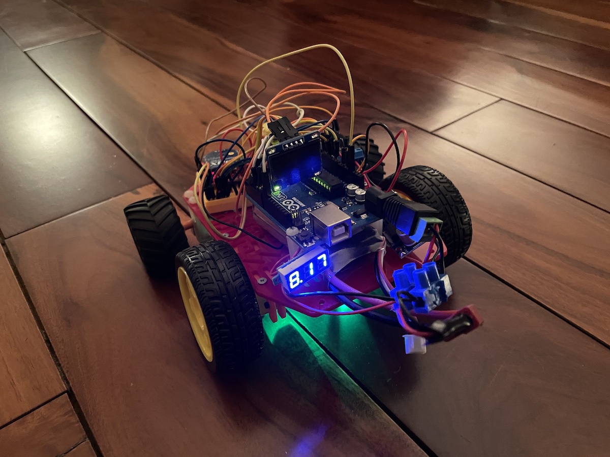
For good measure I attached a tiny OLED on the rover and had it display the active command. Because why not?
Next step: Attach the new gearboxes (old one is definitely broken) and drive this thing remotely. I will also need to calibrate the encoders to make sure it’s travelling the exact distance I expect.
Driving Straight
I made some OK progress on the driving unit last night. I finally got the T connector for the LiPo battery, so I could hook everything up and power both the Arduino and the motors from a portable source.
I was worried about powering them together but it turned out to be simple. I soldered a buck converter (voltage down) between the battery line and the motor shield. Set it up to give out a constant 4.5V, which should be more than enough for the 3V motors I have in there.
Arduino specs say that the power jack can safely handle 7-12V input. This is perfect since the LiPo I’m using is 2S (7.4V). I hooked up the LiPo straight into the Arduino power jack and then split a line out to the buck converter. This also prevents any power backlash from the motor shield. I now have a mobile rover!
Things didn’t go so well on the ground though! Robot immediately swerved left and hit the wall. I suspected this might happen, since the encoders were showing that the right side was clocking half the turns of the left side. After looking (and listening) to the wheels and gears, I think the gear box on the right one is busted.
I ordered some replacement gear boxes and will open up the one I have to see if I can fix it tomorrow.
In the meantime I also hooked up an Xbee S1 module to the unit. Plan is to be able to remotely control it from the computer. Configuring the Xbees was easier than I remembered. X-CTU app is a dumpster fire but once you know how to do a few basic things configuration is fairly easy.
Plan for tomorrow: Implement a simple serial protocol to control the driver unit. I’m imagining a couple of commands for starters: Direction + Distance and Rotation + Angle (ie. F100, B50, R90).
Visualizing LIDAR Data
I had my first try at visualizing incoming data from the LIDAR last night. Good news is that it worked, and I got a successful SLAM map of the room. That’s pretty awesome.

Bad news is I definitely have to redesign the pulley mechanism. Stepper motor is ridiculously loud, heavy and slow. I need to design a smaller pulley system that runs on an encoded DC motor.
I used a Python library called BreezySLAM for the SLAM implementation. It really simplifies the amount of work you have to do. I had to do some figuring out on Python serial comms, but once I got the data from Arduino to Jupyter, I had the image rendered in a few minutes. Here is the relevant piece of code:
import io
import PIL.Image as Image
import IPython.display

MAP_SIZE_PIXELS = 800

from breezyslam.sensors import Laser
from breezyslam.algorithms import RMHC_SLAM

garmin = Laser(332, 4, 360, 4000)

slam = RMHC_SLAM(garmin, MAP_SIZE_PIXELS, 7)

for i in range(TOTAL_SCANS):
    slam.update(scans_mm[i])

map_data = bytearray(MAP_SIZE_PIXELS * MAP_SIZE_PIXELS)

slam.getmap(map_data)

image = Image.frombuffer('L', (MAP_SIZE_PIXELS, MAP_SIZE_PIXELS), map_data, 'raw', 'L', 0, 1)

IPython.display.display(image)
So, success on the software but back to the drawing board on the mechanical. This is not such a big deal, since I can apply the learnings to the new design. Notes for v2:
- Keep pulleys as small as possible
- Reduce timer belt distance to 200mm if possible (currently 400mm)
- Move QRD1114 to the bottom for easier mounting (and hiding the calibration disk)
Encoding Stepper Motor Position
I finally ran into an issue that I have been dreading for a while: Encoding the actual position of the LIDAR pulley mechanism. Now that the LIDAR scan works, I need accurate position data alongside the measurements. As reliable as my ridiculously powerful stepper is, it’s not a servo and doesn’t know which position it starts from.
There are various ways of solving this, with varying levels of budget and difficulty:
- Absolute encoders use code wheels alongside optical or magnetic sensors that have a unique pattern per step. Whatever orientation the wheel is in, the sensors are always able to determine the exact angle.
- Quadratic encoders use two coupled sensors (either magnetic Hall effect sensors or optical ones) to determine wheel direction. They cannot determine absolute position.
- Single optical encoder wheels that rely on a chip such as
LM393are able to determine incremental movement, but not direction. They also cannot determine absolute position.
Unfortunately, among these options, the only one that could work is the absolute encoder. These are hard to find and as far as I can tell quite expensive. One can probably DIY it, but it wouldn’t be a simple implementation.
As I was thinking through this, it occurred to me that all I care about is the starting position. I had initially thought that the stepper motor wouldn’t be reliable, but some quick testing showed that it’s very reliable. Stepper motor is very effective at counting its steps, since that’s literally the main thing it’s good at. So as long as I positioned the starting point properly, I could get accurate positional data.
This is obviously not a novel idea, since all stepper motors work like this. In a 3D printer or CNC machine, the steppers move until they hit the stop switch, which tells the device that it found the starting position. Then it can count its steps from that position and know its exact location.
I really didn’t want to use a physical stop switch, even though I have quite a few lying around from the flip clock project. This got me thinking: Could I use an optical switch instead? I started looking into line tracking robots, since that’s a very similar use case.
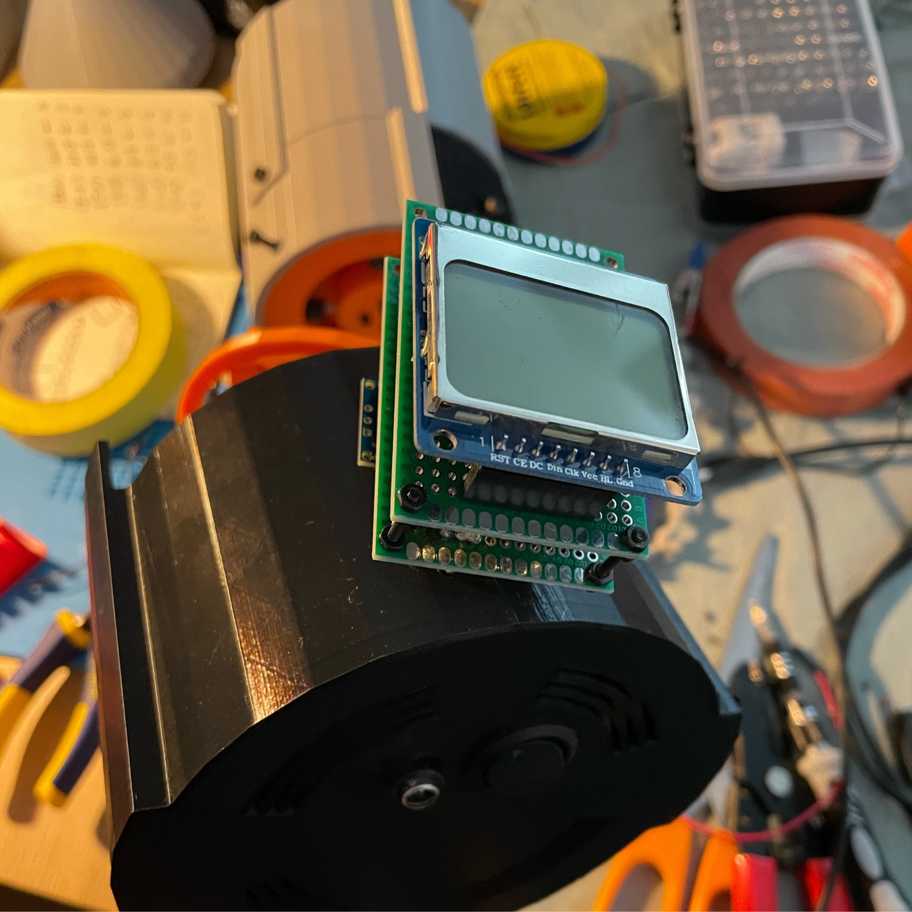
Research led me to the QRD1114 Optical Detector module. The device is a bit of a weird mashup of a phototransistor coupled with an IR detector. The result is that it’s very good at detecting black and white on non-reflective (i.e. standard printer paper) surfaces.
Device looked familiar, so I looked in my sensors box, and got lucky! I already had one. I got to work prototyping it out and got it working very quickly. The Sparkfun guide above was very helpful.
After some trial and error, I ended up preparing a circular drawing with the exact dimensions of the pulley extension in Illustrator. Then I printed this with the laser printer and cut it out. Sensor could detect it very efficiently.

To make the code just as efficient, I used a hardware interrupt whenever the sensor triggers on black:
attachInterrupt(digitalPinToInterrupt(2), detectMark, RISING);
Every time the LIDAR starts running, I run a calibration cycle, determining where the line is. Then I can start scanning from that position and increment with the stepper. Every time the line is detected, position is reset since that means we completed a full circle scan.
Early testing showed very promising results today. I will attempt to create a Processing.org sketch that can visualize the results tomorrow.
Stepper Motor Hell
I got the stepper motor working tonight. This was significantly harder than I expected. I had several motor driver boards lying around, and thought I would make my job easier and use an Arduino Motor Shield. As it turns out, running steppers with it is not that straightforward. I tried several libraries, everything from the standard Stepper library to the AccelStepper, which is supposed to be state of the art.
There are a few things that threw me off, in no particular order:
The NEMA-14 I am using is a 4-cable bipolar motor. I tried to initialize the libraries with pins for all 4 coil cables, and this doesn’t work. Apparently what you are supposed to do is to use the 2-cable setup, but then set the PWM pins to HIGH in setup:
Stepper stepper(stepsPerRevolution, DIR_A, DIR_B);

void setup() {
  pinMode(PWM_A, OUTPUT);
  pinMode(PWM_B, OUTPUT);
  pinMode(BRAKE_A, OUTPUT);
  pinMode(BRAKE_B, OUTPUT);

  digitalWrite(PWM_A, HIGH);
  digitalWrite(PWM_B, HIGH);
  digitalWrite(BRAKE_A, LOW);
  digitalWrite(BRAKE_B, LOW);

  stepper.setSpeed(400);
}
Same idea applies to AccelStepper. Brake pins are needed only because of the Arduino Motor Shield’s setup.
I eventually got the motor to run with the AccelStepper library, but it was very unreliable. Even though I wanted it to run at a constant speed, motor would continuously accelerate or decelerate, and eventually would stall. In addition, I noticed that trying to use Serial during operation was a big problem with AccelStepper. It would change the way the motor was running.
I also ran some tests on the Adafruit Motor Shield rev1 I had from many years ago. Again, I could get the motor to run, but it was unreliable. In addition the board started smelling funny and I noticed that the L293D H-bridge driver getting very hot.
Finally, I decided to get back to basics. I hooked the Arduino Motor Shield up, loaded up the Stepper library again and wrote the simplest stepper program:
void setup() {
    stepper.setSpeed(400);
}

void loop() {
  stepper.step(1);
}
After fiddling with the speed a bit, this actually worked! I elaborated on it a bit more to confirm the RPM:
void loop() {
  stepper.step(1);
  currentStep += 1;

  if (millis() - lastCheckTime >= 60000) {
    Serial.print("RPM: ");
    Serial.println(currentStep / stepsPerRevolution);

    currentStep = 0;
    lastCheckTime = millis();
  }
}
And sure enough, I got an RPM reading of 398. It’s good enough for the LIDAR, and I can safely print things out to the Serial.
Next step will be designing the pulley system. I got the 42mm bearing and the timing belt today. It’s going to be fun to hook up the whole mechanism.
Notes on LIDAR research
I have been researching various ways to build a radar for robotic projects. I already have a Garmin LIDAR Lite I had bought years ago, so LIDAR seems to be the best way to go. However, my research shows that there are several additional parts that are also required:
- A slip ring, to keep the rotating LIDAR module in connection with the rest of the robot
- Some kind of pulley mechanism to rotate the unit
- A stepper motor or a brushed motor for rotation
- In the case of a brushed motor, an encoder would be needed to calculate exact position
- Wide metal bearing of some sort
- A timing belt or similar for pulley
I found several projects that show some level of success with this method:
I couldn’t get my head around how to design the pulley mechanism until I saw this project: DIY Arduino LIDAR. Basically, the slip ring attaches to the base plate and the rotating part is left to turn on its own. Aluminum bearing does the bulk of the work, since it’s inserted between the large pulley wheel, and an extrusion from the base plate.
The Garmin LIDAR Lite can scan at a maximum rate of 500 scans per second! Even if I assumed half that speed, that would be amazing. Unfortunately, I will be limited by the mechanical aspects of the components. The slip ring is rated at 300 RPM. It could go higher, but would start introducing significant noise into the signal. Using a brushed motor with an encoder doesn’t make sense in this scenario, since I wouldn’t require the higher RPM provided by it.
It seems like using one of the NEMA-14 steppers I already have is the best way to go. I have smaller stepper motors from the flipclock project, but they only seem capable of 20-25 RPM at most. NEMA-14 is rated at 600 RPM, with 200 steps per revolution. So here is the plan:
- Get NEMA-14 stepper working reliably, with continuous speed at 300 RPM and reporting its exact position
- Design and print a pulley mechanism connected to the stepper, with the LIDAR attached to the large part
- Have LIDAR scanning with every step and returning distance data, couple stepper position with distance data
- Implement a simple visualizer to show the results
This should get me a simple, 2D live map of the environment. Once I have this, I can start getting into using SLAM algorithms using the ROS platform.
ZoomBox
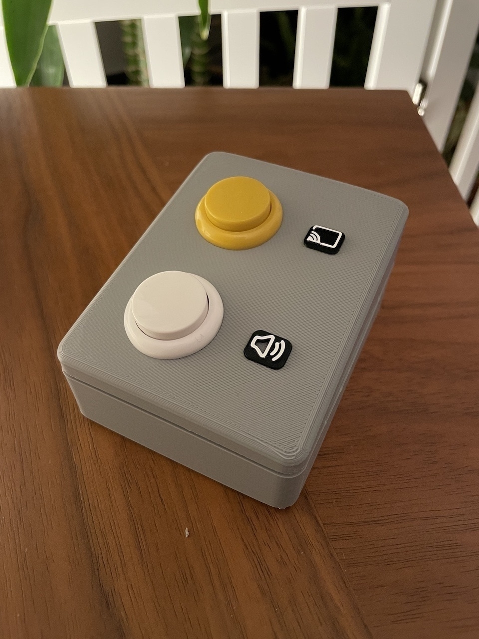
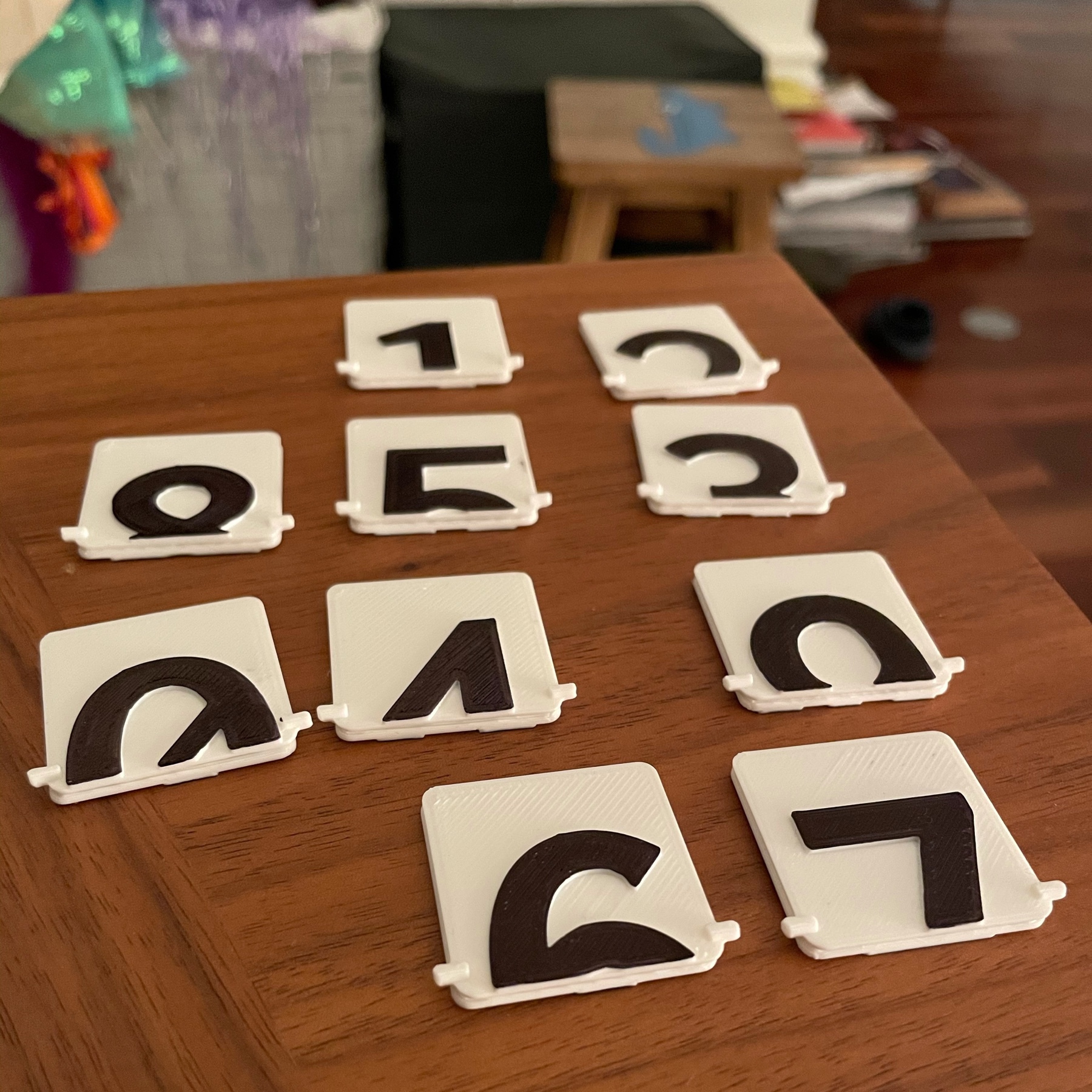
ZoomBox is ready! I designed and printed the top part and fitted the arcade buttons in. I wanted the button icons to be extruded out, which presented a problem. If I extruded them, I couldn’t print the top part upside down. Eventually I decided to print without them and then printed them separately in black filament. Then used a white acrylic pencil to contour the icons. I am pretty happy with the result.
Obviously, using an Arduino UNO for this project is overkill. My research eventually led me to the Arduino Pro Micro, which already has an ATMEGA32u4 in it. This means it’s ready to be used as an HID and all keyboard and mouse control can be done with it.
I will get my hands on some Pro Micros to play with them, but in the meantime this version of the project is a success.
I published all STL models and the Arduino sketch on the ZoomBox Github repo.
Zoom Mute Controller with Arduino
I had a very informative hacking session tonight and quite a few trips down rabbit holes. I decided to do a little side project: A couple of big hardware buttons that can control Zoom mute/unmute and screen share on/off states on my laptop. I spend most of my days on Zoom and it would be very handy.
Easy, right? Well, it turns out that it’s not that easy.
First thing I did was confirming that Zoom already had global hot keys for the controls I needed. Found them under Settings > Keyboard Shortcuts. Looked good.
Then I did some research on Arduino keyboard controlling. Initial results suggested that the Keyboard library included with the Arduino IDE could easily do this. Great!
Finally I hooked up a couple of big push buttons to an Arduino UNO and spent a bit of time on doing a clean button test implementation. I even got double click and long press actions working thanks to the excellent AceButton library.
It was looking like I was about to wrap this project up. That’s when I tried to compile the whole thing and got a weird error: Keyboard.h doesn’t exist.
My first thought was that something went awry with the IDE included libraries. After some digging, I learned that Keyboard and Mouse libraries are not available for Arduino UNO. Some more digging taught me that this was because ATMEGA328p processor was actually incapable of doing USB communication. So essentially I wasn’t able to have the Arduino Uno or none of the other Nanos or Megas I have at home show up to the computer as a USB HID (Human Interface Device).
Some more research brought me to this article and similar articles and YouTube posts that suggested the bootloader on the Arduino UNO could be swapped with a custom bootloader that would allow USB HID protocol on the ATMEGA328p. I went down several rabbit holes, and even loaded up the official Arduino bootloader using dfu-programmer, following the guide on Arduino.cc.
I was hesitant to upload a custom bootloader on the Arduino. Even though you can’t brick it with this method, none of the tutorials I looked at seemed reputable. They each had their own sketchy Github repos with weirdly named hex file downloads. Also most of the articles were at least 5 years old. Things didn’t seem very promising.
Just as I was getting ready to change tracks – I started considering converting this into a Raspberry Pi Pico project, which I just received in the mail – I came across Hoodloader2. Immediately I could see that this is what I was looking for: A well-maintained, open source project that has been around for years. It came with a very detailed wiki but even then it took me an hour to understand what it was actually doing. This is primarily my fault, because apparently I had no idea how the Arduino UNO boards actually worked.
Here is what I learned: The Arduino UNO prototyping boards actually don’t just contain the ATMEGA328p processor, but also a second processor: the ATMEGA16u2 (older ones have the ATMEGA8u2). ATMEGA16u2 and its siblings are small but powerful microprocessors that have embedded USB HID capabilities. The Arduino UNO board essentially uses this secondary chip to do the USB to Serial translation behind the scenes.
This is where Hoodloader’s genius comes in: It’s a custom bootloader you can load up on the ATMEGA16u2 that allows you to load up Arduino sketches on it! This is the part I didn’t initially understand fully. I thought Hoodloader was going to automatically create a bridge between the ATMEGA328p and the new bootloader, so I could use Keyboard libraries directly from the Arduino UNO side. Apparently this is technically possible, but Hoodloader doesn’t do it. So essentially you build a sketch for the 16u2, use its pins (you can have up to 7 digital pins) and essentially run everything in a little corner of the board. You can still upload a secondary sketch to the main Arduino board, but it’s not necessary.
Armed with this knowledge, and by also leveraging NicoHood’s HID library, I was able to get the keyboard input working fairly quickly. I now have a nice little prototype running that can mute and unmut Zoom. More actions can easily be added.
I also did some more research on the ATMEGA16u2 and its bigger brother, ATMEGA32u4. It’s possible to build fairly simple PCBs that use these microprocessors as the brain. That would be a fun little project, and very handy. I’ll dig into this in the upcoming weeks.
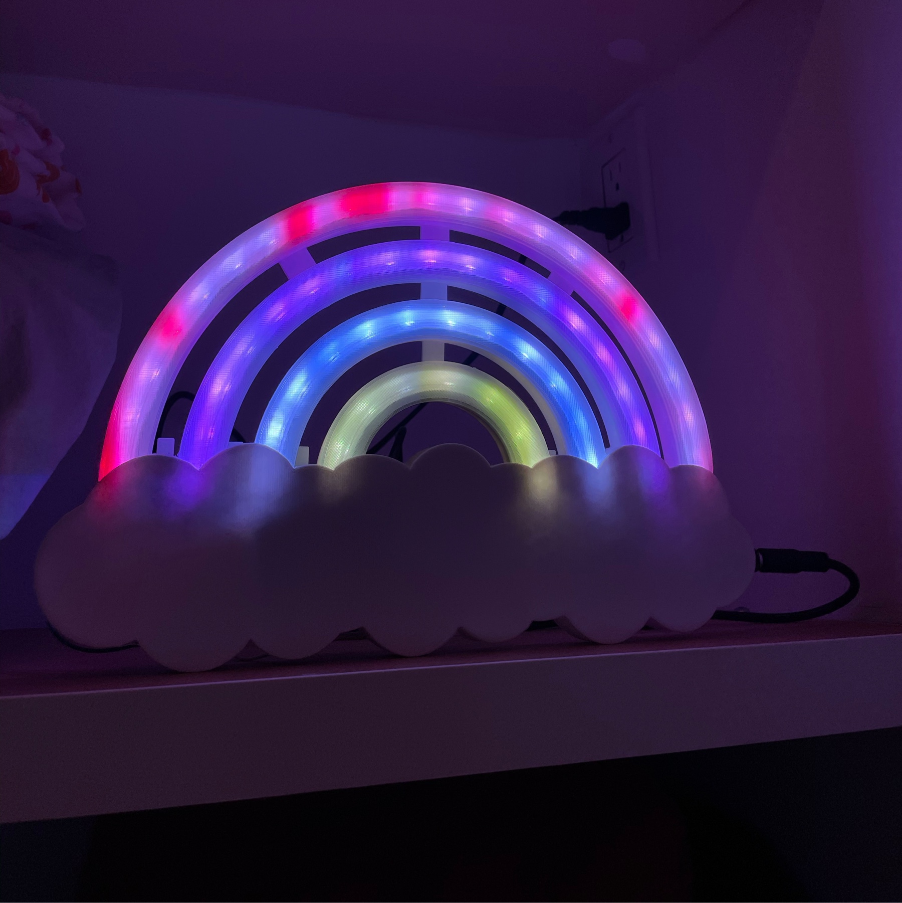
Wrapped up the weekend with a successful test of the Bluetooth controls on LED Rainbow. M changed the colours to her choices (mostly purple). Apparently she is going to draw an app icon for it 😀
Finally found some time last night to place the screen with battery status monitor on the vacuum. Hoping to finalize it tonight!
Bluetooth Rainbows
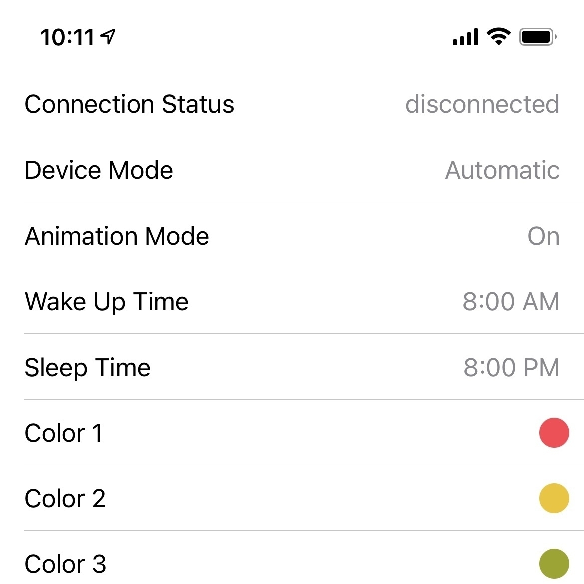
Decided to add Bluetooth control to the LED Rainbow. Every once in a while we need to change the go to sleep and wake up times and M wants to be able to control the colours from her iPad.
Got my old RedBearLab BLE units out. Unfortunately RedBearLab seems to have gone out of business in the last few years. But the units are still working well and thankfully their GitHub repos are still up.
Spent a few hours converting and old BLE library into a working Swift implementation. Next step will be writing a simple protocol to control time and colour settings on the rainbow.
Pretty happy with the progress I made on the workout timer this week. Rotary encoder control feels very smooth and big digits make a difference.
Progress so far is on GitHub with more details on my previous post. Lots more to do this weekend.
Workout Timer Initial Steps
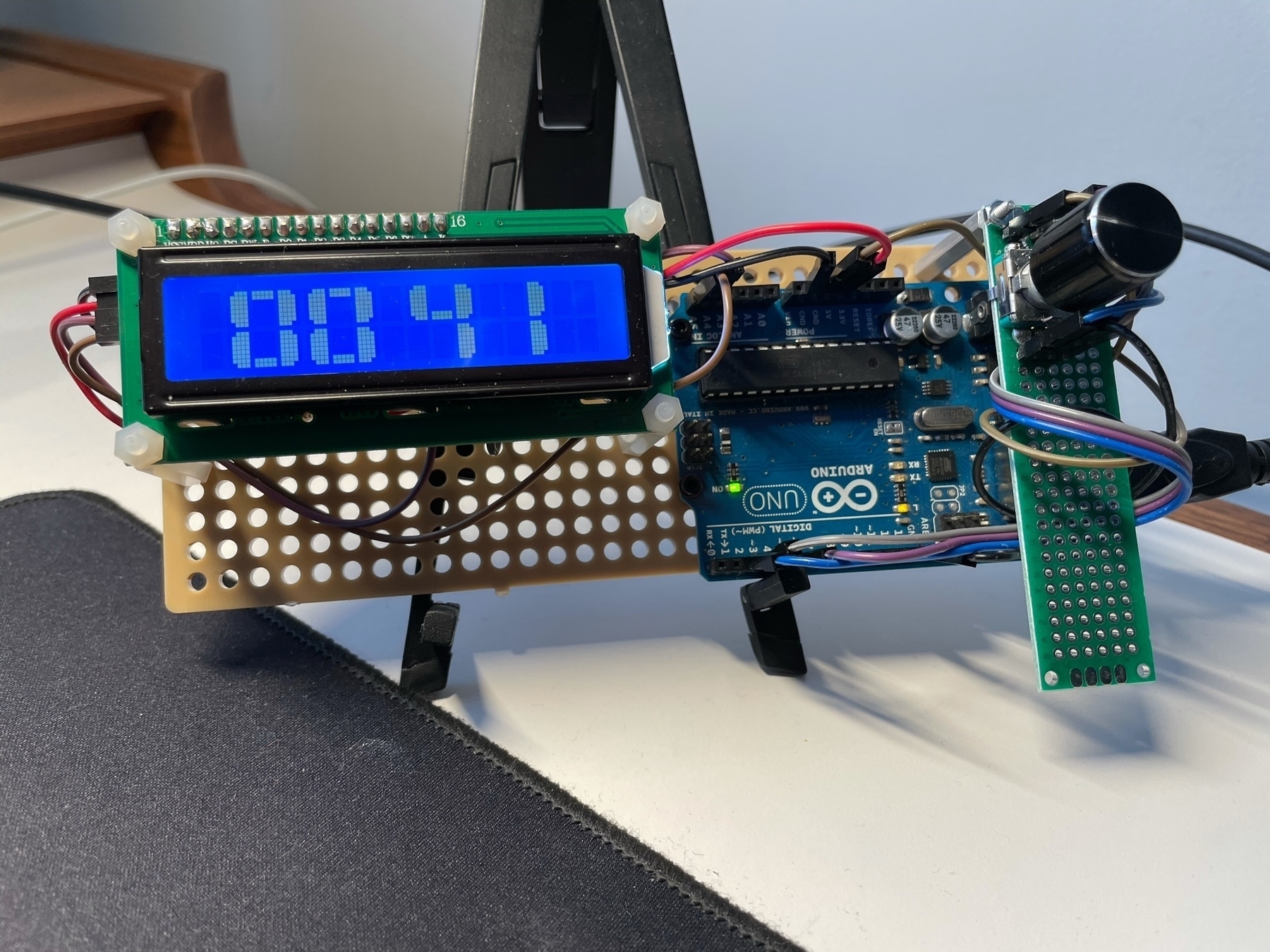
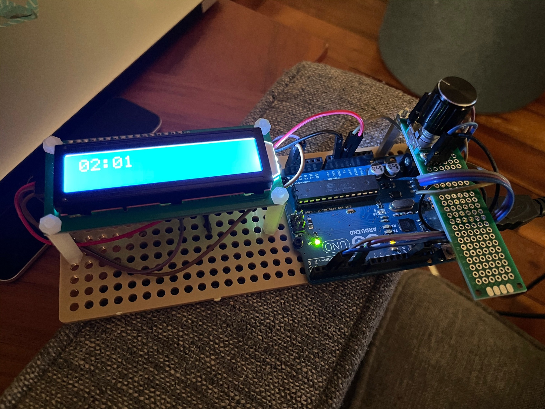
Made some good progress on the workout timer tonight. I have been coding for Arduino for years but I had never bothered to learn the class-based architecture. It takes a bit of getting used to, but being able to organize methods into classes like I normally do at the day job is delightful. I ended up designing a simple and clean architecture for the LCD menu system, as well as the timer itself. As a bonus, I got the large digits working!
A little bit about the large digits: These LCD screens are pretty simple. They essentially have 5x8 blocks that can be filled in using a byte array. This handy tool is great for generating custom characters. I also found this Instructable to be very helpful.
Unfortunately, these characters need to be written to the screen’s memory, and that’s very limited. On the version I have, I only have space for 8 characters. Thankfully, that’s just enough to be able to generate all digits from. I just had to find a bit of a hack to get the large timer colon.
Another thing I worked on was a stable rotary encoder class. There has been some great work done by the community on this, with tons of example code and libraries. Unfortunately, there is almost too much content, and everyone seems to have a different solution to the problem. After dabbling with a few libraries and not getting great results, I found this clear and concise Instructable on the topic and integrated the straightforward implementation into a class-based architecture.
To top it off, I merged this with a standard software button debouncer implementation and ended up with a nice little reusable class for tackling encoders. I am planning to add more “gestures” to this, such as long press and double click.
My progress so far is in this Github repo.
New Project: Workout Timer
Started work on a little side project: A workout timer. I need a simple timer during morning workouts and this is a good challenge for it.
Requirements and problems to solve:
- Smooth rotary encoder feedback (suprisingly hard)
- Large numbers on LCD
- Object oriented menu system
- Battery powered and rechargeable
Built a prototype board with LCD, encoder and Arduino for easy testing. Encoder implementation with interrupt pins already working nicely. Next step: OOB menu system.
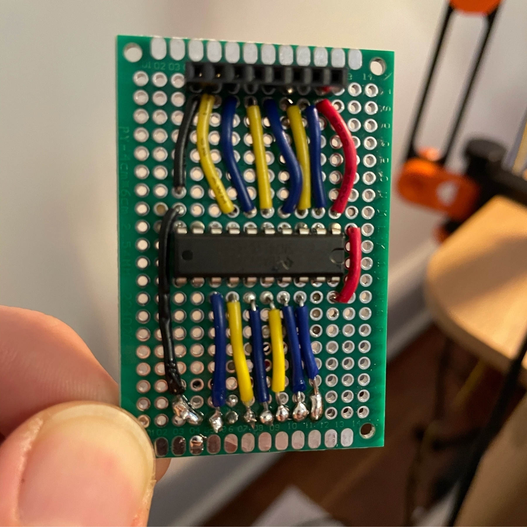
Still have a long way to go, but I’m proud of the improvements in my soldering. Lots of lessons learned:
- Lower heat is better (30W)
- Clean the board and tip
- Use flux for connections
- Utilize both sides of PCB
- Check connectivity with multimeter

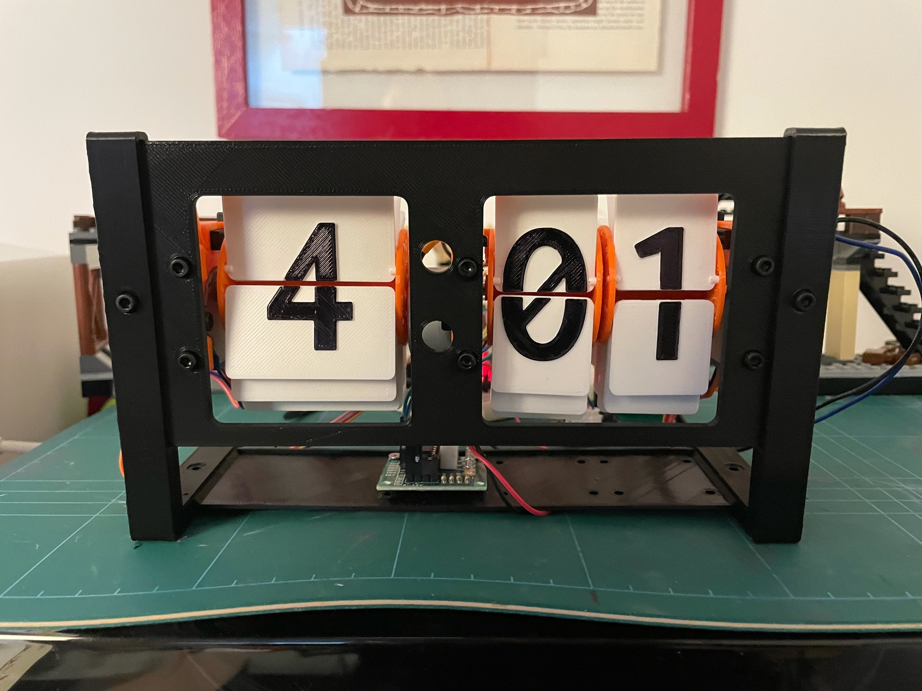
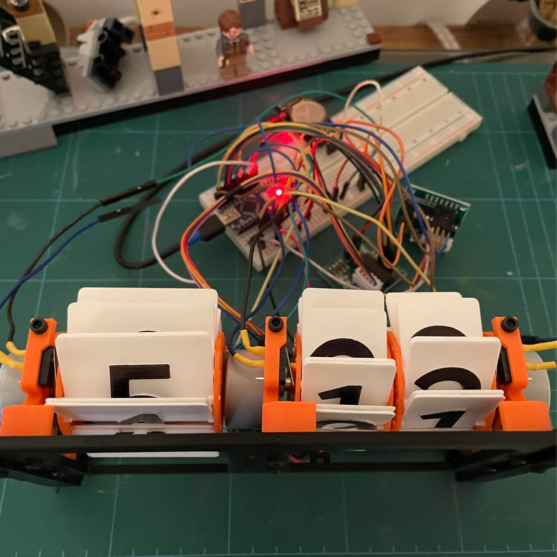
After several minor adjustments, got the first successful version of the flipclock running well. Electronics is a mess that needs to be organized on a PCB, but pretty happy with the results!
Designed and printed a motor holder for a new project I have in mind. Going to experiment with optical encoders and motors to see if I can put together a roaming bot that accurately moves in specific distances.
Flipclock digits are assembled! They are looking clean and beautiful. I will be assembling the full device tomorrow evening and hopefully have it functional.
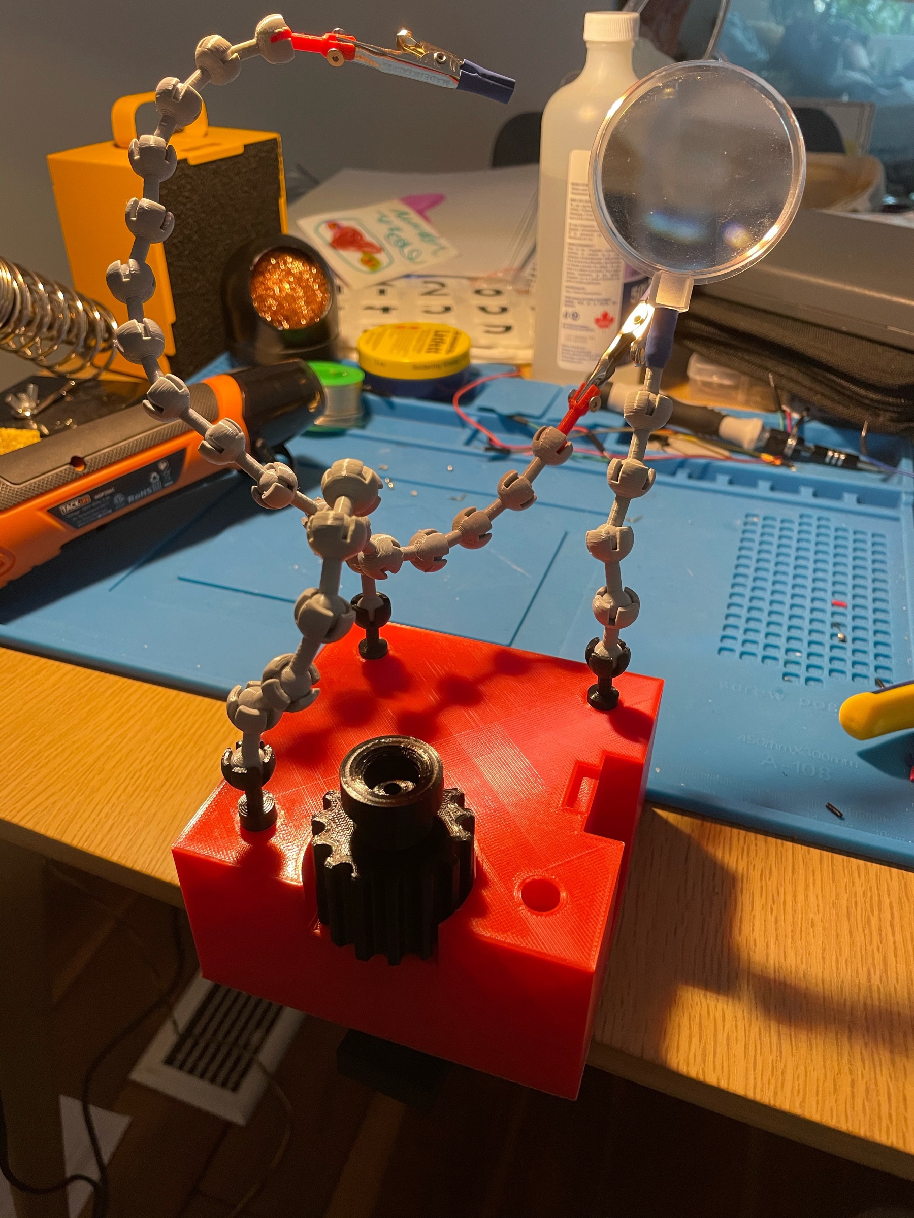
I have some soldering to do this weekend so I decided to improve my setup. After much searching, I found this design on Thingiverse. I modified the base and tips so they fit my alligator clips and can slot in without glue. Pretty happy with the results!
Started to plan out the PCB design for my handheld vacuum’s control unit. Display will show battery state and remaining operation time. Might give EAGLE a try, designing on paper can only go so far.